

GE Consumer & Industrial - G E Power Controls
GE Consumer & Industrial - G E Power Controls
GE Consumer & Industrial - G E Power Controls

You also want an ePaper? Increase the reach of your titles
YUMPU automatically turns print PDFs into web optimized ePapers that Google loves.
4.3 Electrical diagrams<br />
4.3.1 Wiring code<br />
<br />
<br />
<br />
The main circuits are not shown in the wiring diagrams<br />
for transparency. The control circuit is presented as a<br />
typical circuit diagram and is a combination of numbered<br />
basic diagrams for drives, trips and indicators.<br />
Using the key numbers of the basic plan, you can derive<br />
the number of the complete diagram.<br />
WARNING: Some non standard electrical circuits do not<br />
comply with the diagrams in this instruction. Such circuits<br />
are coded with unique numbers i.e 36/0033. In such a<br />
case an appendix to this instruction is delivered, which<br />
contains relevant electrical diagrams.<br />
Coding positions:<br />
Key position:<br />
Breaker type<br />
Aux. voltage supply<br />
ED impulse release<br />
Closing drive<br />
Aux. tripping device<br />
Indicators<br />
Aux. switches<br />
SEL system<br />
1 / 2 3 4 5 6 7 8<br />
Key Key<br />
Designation<br />
position number<br />
Type<br />
1 36 Gerapid<br />
Auxiliary voltage<br />
2 1 Voltage converter<br />
2 DC 24 V external supply<br />
Tripping coil<br />
3 0 Without ed-trip coil<br />
1 With ed-trip coil<br />
2 With ed-trip coil and NEKO<br />
control unit<br />
Drive<br />
4 20 Solenoid drive with<br />
SU control unit<br />
Tripping device<br />
5 00 Without trip unit<br />
10 With shunt trip<br />
20 With zero voltage release<br />
Indication device<br />
6 00 Without indicators<br />
01 OCT trip target<br />
02 Arc chute indicator<br />
03 OCT + arc chute indicator<br />
Auxiliary contacts<br />
7 1 3 auxiliary contacts<br />
2 5 auxiliary contacts<br />
3 10 auxiliary contacts<br />
Current-measurement system<br />
8 S with SEL<br />
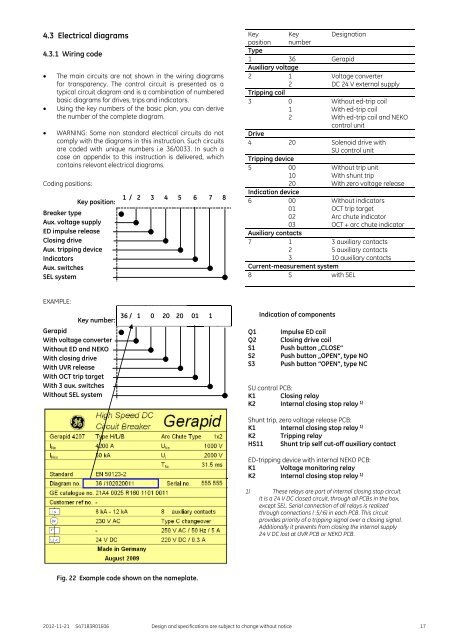
EXAMPLE:<br />
Key number:<br />
Gerapid<br />
With voltage converter<br />
Without ED and NEKO<br />
With closing drive<br />
With UVR release<br />
With OCT trip target<br />
With 3 aux. switches<br />
Without SEL system<br />
36 / 1 0 20 20 01 1<br />
Q1<br />
Q2<br />
S1<br />
S2<br />
S3<br />
Indication of components<br />
Impulse ED coil<br />
Closing drive coil<br />
Push button „CLOSE“<br />
Push button „OPEN“, type NO<br />
Push button “OPEN”, type NC<br />
SU control PCB:<br />
K1 Closing relay<br />
K2 Internal closing stop relay 1)<br />
Shunt trip, zero voltage release PCB:<br />
K1 Internal closing stop relay 1)<br />
K2 Tripping relay<br />
HS11 Shunt trip self cut-off auxiliary contact<br />
ED-tripping device with internal NEKO PCB:<br />
K1 Voltage monitoring relay<br />
K2 Internal closing stop relay 1)<br />
1) These relays are part of internal closing stop circuit.<br />
It is a 24 V DC closed circuit, through all PCBs in the box,<br />
except SEL. Serial connection of all relays is realized<br />
through connections ( :5/:6) in each PCB. This circuit<br />
provides priority of a tripping signal over a closing signal.<br />
Additionally it prevents from closing the internal supply<br />
24 V DC lost at UVR PCB or NEKO PCB.<br />
Fig. 22 Example code shown on the nameplate.<br />
2012-11-21 S47183R01E06 Design and specifications are subject to change without notice 17


