

GE Consumer & Industrial - G E Power Controls
GE Consumer & Industrial - G E Power Controls
GE Consumer & Industrial - G E Power Controls

You also want an ePaper? Increase the reach of your titles
YUMPU automatically turns print PDFs into web optimized ePapers that Google loves.
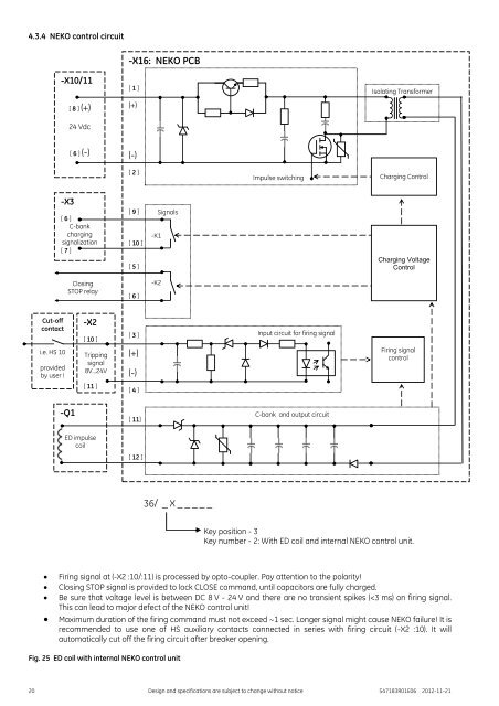
4.3.4 NEKO control circuit<br />
-X10/11<br />
[ 8 ] (+)<br />
24 Vdc<br />
-X16: NEKO PCB<br />
[ 1 ]<br />
(+)<br />
Isolating Transformer<br />
[ 6 ] (-)<br />
(-)<br />
[ 2 ]<br />
Impulse switching<br />
Charging Control<br />
-X3<br />
[ 6 ]<br />
C-bank<br />
charging<br />
signalization<br />
[ 7 ]<br />
[ 9 ]<br />
[ 10 ]<br />
[ 5 ]<br />
-K1<br />
Signals<br />
Charging Voltage<br />
Control<br />
Closing<br />
STOP relay<br />
[ 6 ]<br />
-K2<br />
Cut-off<br />
contact<br />
i.e. HS 10<br />
provided<br />
by user !<br />
-X2<br />
[ 10 ]<br />
Tripping<br />
signal<br />
8V...24V<br />
[ 11 ]<br />
[ 3 ]<br />
(+)<br />
(-)<br />
[ 4 ]<br />
Input circuit for firing signal<br />
Firing signal<br />
control<br />
-Q1<br />
[ 11]<br />
C-bank and output circuit<br />
ED impulse<br />
coil<br />
[ 12 ]<br />
36/ _ X _ _ _ _ _<br />
Key position - 3<br />
Key number - 2: With ED coil and internal NEKO control unit.<br />
<br />
<br />
<br />
<br />
Firing signal at (-X2 :10/:11) is processed by opto-coupler. Pay attention to the polarity!<br />
Closing STOP signal is provided to lock CLOSE command, until capacitors are fully charged.<br />
Be sure that voltage level is between DC 8 V - 24 V and there are no transient spikes (


