

GE Consumer & Industrial - G E Power Controls
GE Consumer & Industrial - G E Power Controls
GE Consumer & Industrial - G E Power Controls

Create successful ePaper yourself
Turn your PDF publications into a flip-book with our unique Google optimized e-Paper software.
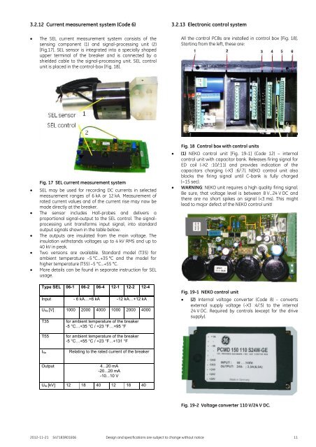
3.2.12 Current measurement system (Code 6)<br />
3.2.13 Electronic control system<br />
<br />
The SEL current measurement system consists of the<br />
sensing component (1) and signal-processing unit (2)<br />
[Fig.17]. SEL sensor is integrated into a specially shaped<br />
upper terminal of the breaker and is connected by a<br />
shielded cable to the signal-processing unit. SEL control<br />
unit is placed in the control-box [Fig. 18].<br />
All the control PCBs are installed in control box [Fig. 18].<br />
Starting from the left, these are:<br />
Fig. 17 SEL current measurement system<br />
SEL may be used for recording DC currents in selected<br />
measurement ranges of 6 kA or 12 kA. Measurement of<br />
rated current values and of the current rise may now be<br />
made directly at the breaker.<br />
The sensor includes Hall-probes and delivers a<br />
proportional signal-output to the SEL control. The signalprocessing<br />
unit transforms input signal, into standard<br />
output signals shown in the table below.<br />
The outputs are insulated from the main voltage. The<br />
insulation withstands voltages up to 4 kV RMS and up to<br />
40 kV in peak.<br />
Two versions are available. Standard model (T35) for<br />
ambient temperature –5 °C…+35 °C and the model for<br />
higher temperature (T55) –5 °C…+55 °C.<br />
More details can be found in separate instruction for SEL<br />
usage.<br />
Type SEL 06-1 06-2 06-4 12-1 12-2 12-4<br />
Input - 6 kA…+6 kA -12 kA…+12 kA<br />
U Ne [V] 1000 2000 4000 1000 2000 4000<br />
T35<br />
for ambient temperature of the breaker<br />
-5 °C…+35 °C / +23 °F…+95 °F<br />
<br />
<br />
Fig. 18 Control box with control units<br />
(1) NEKO control unit [Fig. 19-1] (Code 12) – internal<br />
control unit with capacitor bank. Releases firing signal for<br />
ED coil (-X2 :10/:11) and provides indication of the<br />
capacitors charging (-X3 :6/:7). NEKO control unit also<br />
blocks the firing signal until C-bank is fully charged<br />
(~15 sec).<br />
WARNING: NEKO unit requires a high quality firing signal.<br />
Be sure, that voltage level is between 8 V…24 V DC and<br />
there are no short spikes on signal (


