GE Consumer & Industrial - G E Power Controls
GE Consumer & Industrial - G E Power Controls
GE Consumer & Industrial - G E Power Controls
You also want an ePaper? Increase the reach of your titles
YUMPU automatically turns print PDFs into web optimized ePapers that Google loves.
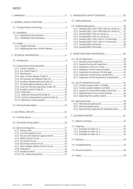
INDEX<br />
1. WARNINGS .............................................................................................. 4<br />
2. <strong>GE</strong>NERAL USA<strong>GE</strong> CONDITIONS ..................................................... 4<br />
2.1 Transportation and storing ....................................................... 4<br />
2.2 Installation .......................................................................................... 5<br />
2.2.1 Operational environment................................................... 5<br />
2.2.2 Installation and interfaces ................................................. 5<br />
2.3 Usage .................................................................................................... 5<br />
2.3.1 Supply and load ...................................................................... 5<br />
2.3.2 Adjusting the over current release................................ 5<br />
3. TECHNICAL INFORMATION .............................................................. 6<br />
3.1 Introduction ....................................................................................... 6<br />
3.2 Components and accessories ................................................. 6<br />
3.2.1 Contact system ....................................................................... 6<br />
3.2.2 Arc chute (Code 2) .................................................................. 6<br />
3.2.3 Mechanism ................................................................................ 7<br />
3.2.4 Over current release (Code 7) ......................................... 7<br />
3.2.5 ED impulse coil release (Code 12) .................................. 8<br />
3.2.6 Auxiliary tripping devices (Code 11) .............................. 8<br />
3.2.7 Forced tripping release (Code 13) .................................. 8<br />
3.2.8 Lever for manual operating (Code 16) ....................... 9<br />
3.2.9 Auxiliary switch (Code 9) .................................................. 10<br />
3.2.10 Indicators .............................................................................. 10<br />
3.2.11 Solenoid closing drive (Code 3) .................................. 10<br />
3.2.12 Current measurement system (Code 6) ................ 11<br />
3.2.13 Electronic control system ............................................. 11<br />
3.3 Technical data tables ................................................................ 13<br />
4. ELECTRICAL CIRCUITS ..................................................................... 15<br />
4.1 <strong>Controls</strong> layout .............................................................................. 15<br />
4.2 Terminals wiring system .......................................................... 16<br />
4.3 Electrical diagrams ..................................................................... 17<br />
4.3.1 Wiring code ............................................................................ 17<br />
4.3.2 <strong>Controls</strong> supply circuit ...................................................... 18<br />
4.3.3 ED coil with external capacity bank .......................... 19<br />
4.3.4 NEKO control circuit ........................................................... 20<br />
4.3.5 SU control circuit ................................................................. 21<br />
4.3.6 Shunt trip control circuit .................................................. 22<br />
4.3.7 Zero voltage release control circuit ........................... 24<br />
4.3.8 Indicators ................................................................................. 25<br />
4.3.9 Auxiliary switch..................................................................... 26<br />
4.3.10 SEL measuring system................................................... 27<br />
5. DIMENSIONS & SAFETY DISTANCES ........................................ 28<br />
5.1 Safety distances. .......................................................................... 29<br />
5.2 Outlined dimensions .................................................................. 30<br />
5.2.1 Gerapid 2607,4207, 6007 with arc chute 1x_...... 30<br />
5.2.2 Gerapid 2607, 4207, 6007with arc chute 2x_...... 31<br />
5.2.3 Gerapid 8007 with arc chute 1x_ ............................... 32<br />
5.2.4 Gerapid 8007 with arc chute 2x_ ............................... 33<br />
5.2.5 Gerapid 2607, 4207 with H / H terminals ............... 34<br />
5.2.6 Gerapid 2607, 4207 with V / V terminals ................ 35<br />
5.2.7 Gerapid 6007 terminals ................................................... 36<br />
5.2.8 Gerapid 8007 terminals ................................................... 37<br />
6. INSPECTIONS AND MAINTENANCE .......................................... 38<br />
6.1 List of inspections ........................................................................ 38<br />
6.1.1 General visual inspection ............................................... 39<br />
6.1.2 General functional inspection ...................................... 39<br />
6.1.3 Inspection of the arc chute ............................................ 39<br />
6.1.4 Inspection of the contact system ............................... 40<br />
6.1.5 Inspection of contacts’ tilt and gap .......................... 41<br />
6.1.6 Inspection of the screw connections ....................... 41<br />
6.1.7 Inspection of the mechanical components .......... 41<br />
6.2 List of maintenance works ..................................................... 42<br />
6.2.1 Contact system (after 11/2003)................................... 43<br />
6.2.2. Contact system (before 11/2003). .............................. 44<br />
6.2.3 Layout of control PCB inside control box ............... 46<br />
6.2.4 Replacement of the control boards .......................... 46<br />
6.2.5 Adjusting the auxiliary switch ...................................... 48<br />
6.3 Spare parts lists. ........................................................................... 49<br />
6.3.1 Mechanical spare parts. .................................................. 49<br />
6.3.2 Electrical spare parts. ....................................................... 50<br />
6.3.3 Recommend materials for selected works. .......... 50<br />
7. CUSTOMER SUPPORT ..................................................................... 51<br />
7.1 Options overview. ........................................................................ 51<br />
7.2 Ordering. .......................................................................................... 52<br />
7.2.1 Example of order no. 1 ..................................................... 53<br />
7.2.2 Example of order no. 2 ..................................................... 54<br />
7.2.3 Example of order no. 3 ..................................................... 55<br />
7.3 Glossary ............................................................................................ 56<br />
7.4 Troubleshooting ........................................................................... 57<br />
7.5 <strong>GE</strong> service teams ......................................................................... 58<br />
7.6 Notes .................................................................................................. 59<br />
2012-11-21 S47183R01E06 Design and specifications are subject to change without notice 3


