

GE Consumer & Industrial - G E Power Controls
GE Consumer & Industrial - G E Power Controls
GE Consumer & Industrial - G E Power Controls

You also want an ePaper? Increase the reach of your titles
YUMPU automatically turns print PDFs into web optimized ePapers that Google loves.
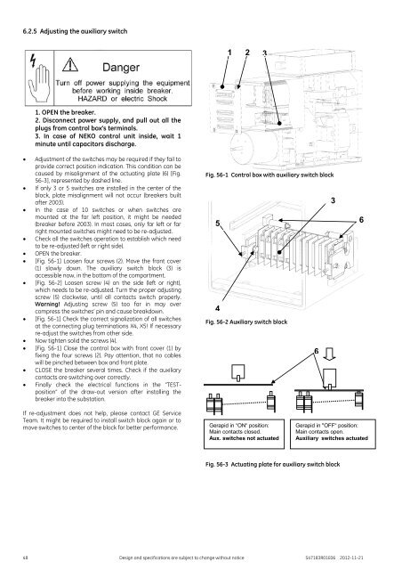
6.2.5 Adjusting the auxiliary switch<br />
1 2 3<br />
<br />
<br />
<br />
<br />
<br />
<br />
<br />
<br />
1. OPEN the breaker.<br />
2. Disconnect power supply, and pull out all the<br />
plugs from control box’s terminals.<br />
3. In case of NEKO control unit inside, wait 1<br />
minute until capacitors discharge.<br />
Adjustment of the switches may be required if they fail to<br />
provide correct position indication. This condition can be<br />
caused by misalignment of the actuating plate (6) [Fig.<br />
56-3], represented by dashed line.<br />
If only 3 or 5 switches are installed in the center of the<br />
block, plate misalignment will not occur (breakers built<br />
after 2003).<br />
In the case of 10 switches or when switches are<br />
mounted at the far left position, it might be needed<br />
(breaker before 2003). In most cases, only far left or far<br />
right mounted switches might need to be re-adjusted.<br />
Check all the switches operation to establish which need<br />
to be re-adjusted (left or right side).<br />
OPEN the breaker.<br />
[Fig. 56-1] Loosen four screws (2). Move the front cover<br />
(1) slowly down. The auxiliary switch block (3) is<br />
accessible now, in the bottom of the compartment.<br />
[Fig. 56-2] Loosen screw (4) on the side (left or right),<br />
which needs to be re-adjusted. Turn the proper adjusting<br />
screw (5) clockwise, until all contacts switch properly.<br />
Warning! Adjusting screw (5) too far in may over<br />
compress the switches’ pin and cause breakdown.<br />
[Fig. 56-1] Check the correct signalization of all switches<br />
at the connecting plug terminations X4, X5! If necessary<br />
re-adjust the switches from other side.<br />
Now tighten solid the screws (4).<br />
[Fig. 56-1] Close the control box with front cover (1) by<br />
fixing the four screws (2). Pay attention, that no cables<br />
will be pinched between box and front plate.<br />
<br />
<br />
CLOSE the breaker several times. Check if the auxiliary<br />
contacts are switching over correctly.<br />
Finally check the electrical functions in the “TESTposition”<br />
of the draw-out version after installing the<br />
breaker into the substation.<br />
Fig. 56-1 Control box with auxiliary switch block<br />
5<br />
4<br />
Fig. 56-2 Auxiliary switch block<br />
3<br />
6<br />
6<br />
If re-adjustment does not help, please contact <strong>GE</strong> Service<br />
Team. It might be required to install switch block again or to<br />
move switches to center of the block for better performance.<br />
Gerapid in “ON“ position:<br />
Main contacts closed.<br />
Aux. switches not actuated<br />
Gerapid in "OFF“ position:<br />
Main contacts open.<br />
Auxiliary switches actuated<br />
Fig. 56-3 Actuating plate for auxiliary switch block<br />
48 Design and specifications are subject to change without notice S47183R01E06 2012-11-21


