

GE Consumer & Industrial - G E Power Controls
GE Consumer & Industrial - G E Power Controls
GE Consumer & Industrial - G E Power Controls

Create successful ePaper yourself
Turn your PDF publications into a flip-book with our unique Google optimized e-Paper software.
3. Technical information<br />
3.1 Introduction<br />
3.2 Components and accessories<br />
3.2.1 Contact system<br />
Gerapid is a high-speed DC circuit breaker. This is a<br />
single-pole DC breaker, primarily designed for use in<br />
railway power distribution systems with operating<br />
currents up to 8000 A (Code 1) and operating voltages up<br />
to 3600 V (Code 2). Additional applications are special<br />
industrial plants such as electrolysis, mining or steel mills.<br />
Gerapid breaker has a very high interruption capacity<br />
combined with a current limiting characteristic. The arc<br />
chute works on the basis of an asbestos-free arc splitting<br />
principle.<br />
A wide variety of accessories and spares are available for<br />
maintenance, repair, or as a possible enhancement.<br />
Use the catalogue coding system described in section 7.1<br />
to configure the breaker. Each rating, option or accessory<br />
has own code.<br />
Closing of the circuit breaker is performed through a highpower<br />
solenoid drive (Code 3).<br />
During inspections, opening and closing may be carried<br />
out by means of a hand lever (Code 16), which is mounted<br />
onto the armature of the closing drive.<br />
Overload tripping and release is obtained directly by<br />
means of the OCT release (Code 7), or optionally by ED<br />
impulse release (Code 12). Indirect remote tripping can be<br />
achieved by means of a shunt trip, or optionally by a zero<br />
voltage release (Code 11).<br />
Gerapid breakers have a compact and enclosed<br />
construction [Fig. 4]. Gerapid is IP 00 protected. All parts<br />
are mounted on thick-walled, non-breakable and<br />
fireproof insulation panels.<br />
<br />
<br />
<br />
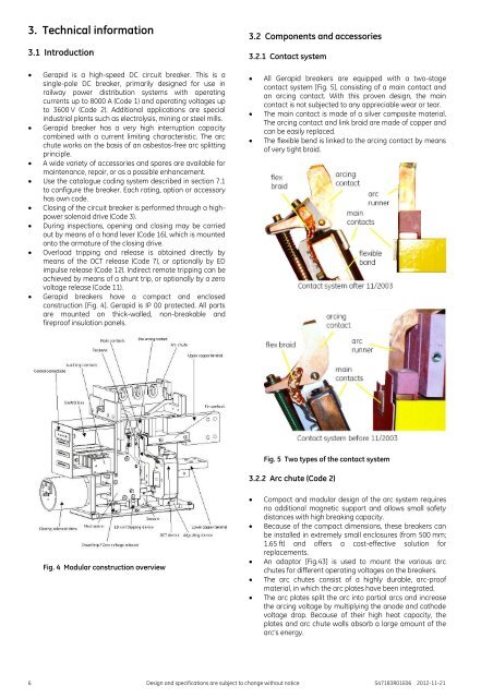
All Gerapid breakers are equipped with a two-stage<br />
contact system [Fig. 5], consisting of a main contact and<br />
an arcing contact. With this proven design, the main<br />
contact is not subjected to any appreciable wear or tear.<br />
The main contact is made of a silver composite material.<br />
The arcing contact and link braid are made of copper and<br />
can be easily replaced.<br />
The flexible bend is linked to the arcing contact by means<br />
of very tight braid.<br />
Fig. 5 Two types of the contact system<br />
3.2.2 Arc chute (Code 2)<br />
Fig. 4 Modular construction overview<br />
<br />
<br />
<br />
<br />
<br />
Compact and modular design of the arc system requires<br />
no additional magnetic support and allows small safety<br />
distances with high breaking capacity.<br />
Because of the compact dimensions, these breakers can<br />
be installed in extremely small enclosures (from 500 mm;<br />
1.65 ft) and offers a cost-effective solution for<br />
replacements.<br />
An adaptor [Fig.43] is used to mount the various arc<br />
chutes for different operating voltages on the breakers.<br />
The arc chutes consist of a highly durable, arc-proof<br />
material, in which the arc plates have been integrated.<br />
The arc plates split the arc into partial arcs and increase<br />
the arcing voltage by multiplying the anode and cathode<br />
voltage drop. Because of their high heat capacity, the<br />
plates and arc chute walls absorb a large amount of the<br />
arc’s energy.<br />
6 Design and specifications are subject to change without notice S47183R01E06 2012-11-21


