

GE Consumer & Industrial - G E Power Controls
GE Consumer & Industrial - G E Power Controls
GE Consumer & Industrial - G E Power Controls

You also want an ePaper? Increase the reach of your titles
YUMPU automatically turns print PDFs into web optimized ePapers that Google loves.
6.1.1 General visual inspection<br />
<br />
<br />
<br />
<br />
<br />
<br />
<br />
<br />
Check out for damages or cracks of the frame, the<br />
adapter or the arc chute.<br />
Check out the black marks on the countersunk screws.<br />
These marks shall be aligned together. If any screw is<br />
loosening, shall be replaced with new one, using Loctite<br />
222. Afterwards, mark the screw with black line to sign<br />
its position in nest.<br />
Check out for missing screws or caps.<br />
Check out for damaged labels. Clean and repair.<br />
Check out for corrosion. In case of significant corrosion,<br />
please contact <strong>GE</strong> representative for assistance.<br />
Check out for distinct manifestations of flame or smoke<br />
at the frame. Especially in lower area of the breaker.<br />
Please document and contact <strong>GE</strong> representative for<br />
assistance.<br />
Clean the breaker of dirt and dust. Remove all dirt with a<br />
dry cloth. No particularly high signs of abrasion (rough<br />
chips) should be visible anywhere.<br />
Clean and degrease the copper terminals.<br />
6.1.2 General functional inspection<br />
<br />
Pay attention to the warnings, Section 1!<br />
In order to check the latch mechanism, the breaker can<br />
be opened and closed with a hand lever.<br />
<br />
<br />
Re-energize the control circuits and switch the breaker<br />
ON and OFF several times using ST or UVR, and using<br />
closing drive. The contacts must close after the CLOSE<br />
command and must open following the OPEN command<br />
The breaker mechanism must not appear sluggish nor<br />
must ON/OFF be unduly delayed.<br />
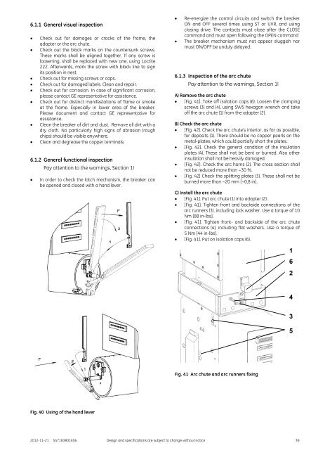
6.1.3 Inspection of the arc chute<br />
Pay attention to the warnings, Section 1!<br />
A) Remove the arc chute<br />
[Fig. 41]. Take off isolation caps (6). Loosen the clamping<br />
screws (3) and (4), using SW5 hexagon wrench and take<br />
off the arc chute (1) from the adapter (2).<br />
B) Check the arc chute<br />
[Fig. 42]. Check the arc chute’s interior, as far as possible,<br />
for deposits (1). There should be no copper pearls on the<br />
metal-plates, which could partially short the plates.<br />
[Fig. 42]. Check the general condition of the insulation<br />
plates (4). These shall not be bent or burned. Also other<br />
insulation shall not be heavily damaged.<br />
[Fig. 42]. Check the arc horns (2). The cross section shall<br />
not be reduced more than ~30 %.<br />
[Fig. 42] Check the splitting plates (3). These shall not be<br />
burned more than ~20 mm [~0,8 in].<br />
C) Install the arc chute<br />
[Fig. 41]. Put arc chute (1) into adapter (2).<br />
[Fig. 41]. Tighten front and backside connections of the<br />
arc runners (3), including lock washer. Use a torque of 10<br />
Nm [88 in-lbs].<br />
[Fig. 41]. Tighten front- and backside of the arc chute<br />
connections (4), including flat washers. Use a torque of<br />
5 Nm [44 in-lbs].<br />
[Fig. 41]. Put on isolation caps (6).<br />
1<br />
6<br />
2<br />
4<br />
3<br />
5<br />
Fig. 41 Arc chute and arc runners fixing<br />
Fig. 40 Using of the hand lever<br />
2012-11-21 S47183R01E06 Design and specifications are subject to change without notice 39


