

GE Consumer & Industrial - G E Power Controls
GE Consumer & Industrial - G E Power Controls
GE Consumer & Industrial - G E Power Controls

You also want an ePaper? Increase the reach of your titles
YUMPU automatically turns print PDFs into web optimized ePapers that Google loves.
3.2.3 Mechanism<br />
<br />
<br />
<br />
<br />
<br />
The Gerapid is equipped with a modular designed<br />
mechanism, which is wear-resistant and nearly<br />
maintenance-free. This mechanism ensures an extended<br />
electrical and mechanical endurance of the breaker as<br />
well as a high level of safety under all operation<br />
conditions.<br />
Breaker can operate 20 000 cycles when opened by the<br />
shunt trip or zero voltage release, and 1 000 operations<br />
by means of ED impulse coil or OCT releases.<br />
This mechanism is mechanically latched in the CLOSED<br />
position. The principle of a mechanically latched<br />
mechanism offers a big advantage compared to often<br />
used electro magnet holding system. No auxiliary control<br />
power source is required to keep breaker closed.<br />
The mechanism is provided with two tripping latches<br />
[Fig. 6]. First latch, called “slow latch”, is used for opening<br />
under normal conditions, like actuation of shunt trip or<br />
zero-voltage release. The second one, “quick latch”, declutches<br />
the main contact arm from the mechanism and<br />
opens the contacts with an extremely short delay. This is<br />
used when interrupting short-circuit or overloads. All<br />
safety releases operate onto “quick latch” latch.<br />
Different main springs are used in mechanisms for<br />
different breaker frames. Therefore mechanisms cannot<br />
be exchange between breakers of different frame.<br />
<br />
<br />
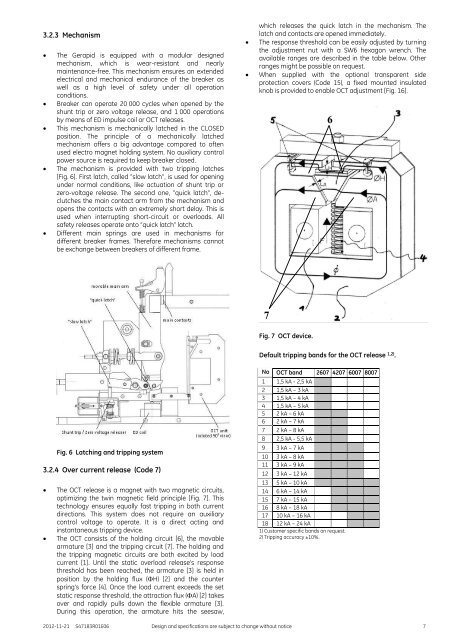
which releases the quick latch in the mechanism. The<br />
latch and contacts are opened immediately.<br />
The response threshold can be easily adjusted by turning<br />
the adjustment nut with a SW6 hexagon wrench. The<br />
available ranges are described in the table below. Other<br />
ranges might be possible on request.<br />
When supplied with the optional transparent side<br />
protection covers (Code 15), a fixed mounted insulated<br />
knob is provided to enable OCT adjustment [Fig. 16].<br />
6<br />
7<br />
Fig. 7 OCT device.<br />
Default tripping bands for the OCT release 1,2) .<br />
Fig. 6 Latching and tripping system<br />
3.2.4 Over current release (Code 7)<br />
<br />
<br />
The OCT release is a magnet with two magnetic circuits,<br />
optimizing the twin magnetic field principle [Fig. 7]. This<br />
technology ensures equally fast tripping in both current<br />
directions. This system does not require an auxiliary<br />
control voltage to operate. It is a direct acting and<br />
instantaneous tripping device.<br />
The OCT consists of the holding circuit [6], the movable<br />
armature [3] and the tripping circuit [7]. The holding and<br />
the tripping magnetic circuits are both excited by load<br />
current [1]. Until the static overload release’s response<br />
threshold has been reached, the armature [3] is held in<br />
position by the holding flux (H) [2] and the counter<br />
spring’s force [4]. Once the load current exceeds the set<br />
static response threshold, the attraction flux (A) [2] takes<br />
over and rapidly pulls down the flexible armature [3].<br />
During this operation, the armature hits the seesaw,<br />
No OCT band 2607 4207 6007 8007<br />
1 1,5 kA - 2,5 kA<br />
2 1,5 kA – 3 kA<br />
3 1,5 kA – 4 kA<br />
4 1,5 kA – 5 kA<br />
5 2 kA – 6 kA<br />
6 2 kA – 7 kA<br />
7 2 kA – 8 kA<br />
8 2,5 kA - 5,5 kA<br />
9 3 kA – 7 kA<br />
10 3 kA – 8 kA<br />
11 3 kA – 9 kA<br />
12 3 kA – 12 kA<br />
13 5 kA – 10 kA<br />
14 6 kA – 14 kA<br />
15 7 kA – 15 kA<br />
16 8 kA – 18 kA<br />
17 10 kA – 16 kA<br />
18 12 kA – 24 kA<br />
1) Customer specific bands on request.<br />
2) Tripping accuracy ±10%.<br />
2012-11-21 S47183R01E06 Design and specifications are subject to change without notice 7


