

GE Consumer & Industrial - G E Power Controls
GE Consumer & Industrial - G E Power Controls
GE Consumer & Industrial - G E Power Controls

Create successful ePaper yourself
Turn your PDF publications into a flip-book with our unique Google optimized e-Paper software.
6.2.1 Contact system (after 11/2003).<br />
Pay attention to the warnings, Section 1!<br />
This section is valid for breakers manufactured after<br />
11/2003.<br />
This section refers to maintenance works A, B, C from<br />
Table 4.<br />
1 3<br />
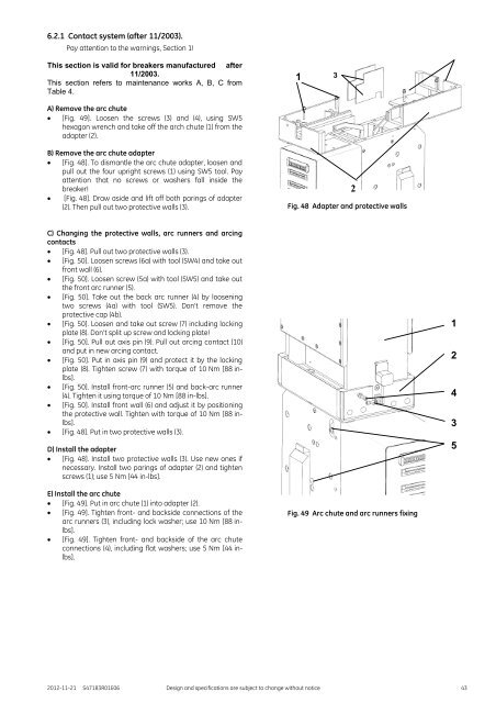
A) Remove the arc chute<br />
[Fig. 49]. Loosen the screws (3) and (4), using SW5<br />
hexagon wrench and take off the arch chute (1) from the<br />
adapter (2).<br />
B) Remove the arc chute adapter<br />
[Fig. 48]. To dismantle the arc chute adapter, loosen and<br />
pull out the four upright screws (1) using SW5 tool. Pay<br />
attention that no screws or washers fall inside the<br />
breaker!<br />
[Fig. 48]. Draw aside and lift off both parings of adapter<br />
(2). Then pull out two protective walls (3).<br />
Fig. 48 Adapter and protective walls<br />
2<br />
C) Changing the protective walls, arc runners and arcing<br />
contacts<br />
[Fig. 48]. Pull out two protective walls (3).<br />
[Fig. 50]. Loosen screws (6a) with tool (SW4) and take out<br />
front wall (6).<br />
[Fig. 50]. Loosen screw (5a) with tool (SW5) and take out<br />
the front arc runner (5).<br />
[Fig. 50]. Take out the back arc runner (4) by loosening<br />
two screws (4a) with tool (SW5). Don’t remove the<br />
protective cap (4b).<br />
[Fig. 50]. Loosen and take out screw (7) including locking<br />
plate (8). Don’t split up screw and locking plate!<br />
[Fig. 50]. Pull out axis pin (9). Pull out arcing contact (10)<br />
and put in new arcing contact.<br />
[Fig. 50]. Put in axis pin (9) and protect it by the locking<br />
plate (8). Tighten screw (7) with torque of 10 Nm [88 inlbs].<br />
[Fig. 50]. Install front-arc runner (5) and back-arc runner<br />
(4). Tighten it using torque of 10 Nm [88 in-lbs].<br />
[Fig. 50]. Install front wall (6) and adjust it by positioning<br />
the protective wall. Tighten with torque of 10 Nm [88 inlbs].<br />
[Fig. 48]. Put in two protective walls (3).<br />
D) Install the adapter<br />
[Fig. 48]. Install two protective walls (3). Use new ones if<br />
necessary. Install two parings of adapter (2) and tighten<br />
screws (1); use 5 Nm [44 in-lbs].<br />
1<br />
2<br />
4<br />
3<br />
5<br />
E) Install the arc chute<br />
[Fig. 49]. Put in arc chute (1) into adapter (2).<br />
[Fig. 49]. Tighten front- and backside connections of the<br />
arc runners (3), including lock washer; use 10 Nm [88 inlbs].<br />
[Fig. 49]. Tighten front- and backside of the arc chute<br />
connections (4), including flat washers; use 5 Nm [44 inlbs].<br />
Fig. 49 Arc chute and arc runners fixing<br />
2012-11-21 S47183R01E06 Design and specifications are subject to change without notice 43


