Laboratory Manual - King Fahd University of Petroleum and Minerals
Laboratory Manual - King Fahd University of Petroleum and Minerals
Laboratory Manual - King Fahd University of Petroleum and Minerals

Create successful ePaper yourself
Turn your PDF publications into a flip-book with our unique Google optimized e-Paper software.
where R R 1<br />
// R 2<br />
// r <strong>and</strong> '<br />
in B B 1<br />
RL<br />
RL<br />
// RC1<br />
2. The low frequency pole can be approximated by the pole due to the capacitor<br />
assoiciated with the lowest resistance namely C E :<br />
1<br />
wL<br />
<br />
(2)<br />
r<br />
RS<br />
// RB<br />
1<br />
// RB2<br />
CE<br />
( RE1<br />
//<br />
)<br />
1<br />
<br />
3. The high frequency pole can be approximated by the pole due to input capacitance<br />
which becomes significantly large because <strong>of</strong> miller’s capacitance C eq = C '<br />
(1 g R m<br />
)<br />
1 eq in s 1<br />
m L in s<br />
1 L<br />
:<br />
1<br />
1<br />
wH<br />
<br />
(3)<br />
'<br />
[ C C ] R // R C g R ( R // R )<br />
'<br />
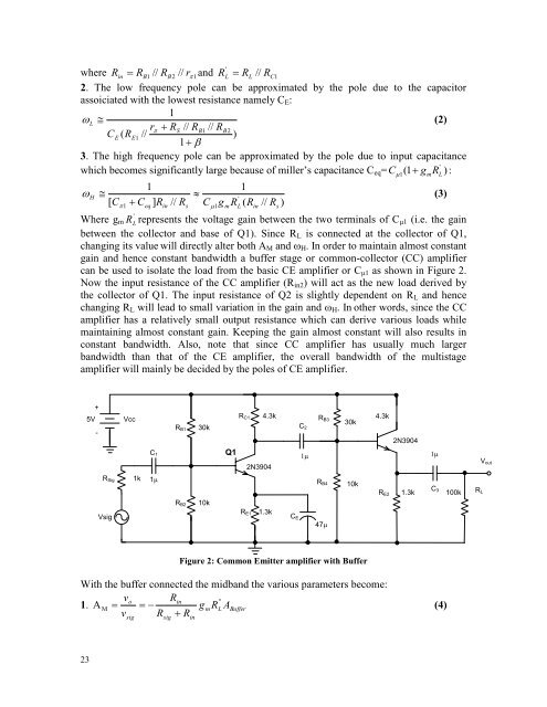
Where g m RL<br />
represents the voltage gain between the two terminals <strong>of</strong> C μ1 (i.e. the gain<br />
between the collector <strong>and</strong> base <strong>of</strong> Q1). Since R L is connected at the collector <strong>of</strong> Q1,<br />
changing its value will directly alter both A M <strong>and</strong> ω H . In order to maintain almost constant<br />
gain <strong>and</strong> hence constant b<strong>and</strong>width a buffer stage or common-collector (CC) amplifier<br />
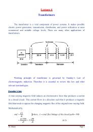
can be used to isolate the load from the basic CE amplifier or C μ1 as shown in Figure 2.<br />
Now the input resistance <strong>of</strong> the CC amplifier (R in2 ) will act as the new load derived by<br />
the collector <strong>of</strong> Q1. The input resistance <strong>of</strong> Q2 is slightly dependent on R L <strong>and</strong> hence<br />
changing R L will lead to small variation in the gain <strong>and</strong> ω H . In other words, since the CC<br />
amplifier has a relatively small output resistance which can derive various loads while<br />
maintaining almost constant gain. Keeping the gain almost constant will also results in<br />
constant b<strong>and</strong>width. Also, note that since CC amplifier has usually much larger<br />
b<strong>and</strong>width than that <strong>of</strong> the CE amplifier, the overall b<strong>and</strong>width <strong>of</strong> the multistage<br />
amplifier will mainly be decided by the poles <strong>of</strong> CE amplifier.<br />
+<br />
5V<br />
-<br />
R Sig<br />
Vsig<br />
Vcc<br />
1k<br />
C 1<br />
1<br />
R B1<br />
R C1 4.3k<br />
30k<br />
C 2<br />
Q1<br />
1<br />
2N3904<br />
R B2 10k<br />
R E1 1.3k<br />
C E<br />
R B3<br />
R B4<br />
47<br />
30k<br />
10k<br />
4.3k<br />
R E2<br />
2N3904<br />
1<br />
C 3<br />
1.3k 100k R L<br />
V out<br />
Figure 2: Common Emitter amplifier with Buffer<br />
With the buffer connected the midb<strong>and</strong> the various parameters become:<br />
v<br />
o<br />
Rin<br />
''<br />
1. A M<br />
g<br />
mRL<br />
ABuffer<br />
(4)<br />
v R R<br />
sig<br />
sig<br />
in<br />
23