Laboratory Manual - King Fahd University of Petroleum and Minerals
Laboratory Manual - King Fahd University of Petroleum and Minerals
Laboratory Manual - King Fahd University of Petroleum and Minerals

You also want an ePaper? Increase the reach of your titles
YUMPU automatically turns print PDFs into web optimized ePapers that Google loves.
KING FAHD UNIVERSITY OF PETROLEUM AND MINERALS<br />
DEPARTMENT OF ELECTRICAL ENGINEERING<br />
Electronic Circuits II – EE303<br />
Experiment # 3<br />
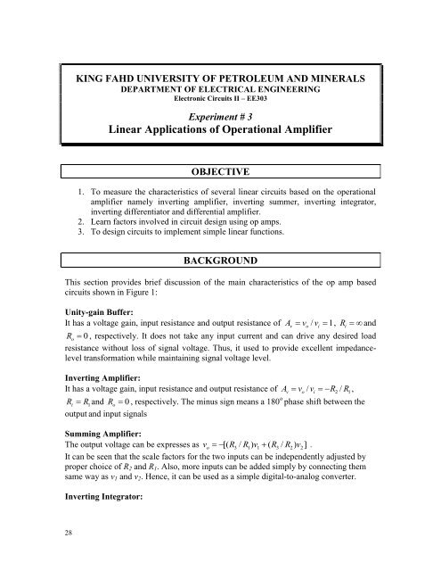
Linear Applications <strong>of</strong> Operational Amplifier<br />
OBJECTIVE<br />
1. To measure the characteristics <strong>of</strong> several linear circuits based on the operational<br />
amplifier namely inverting amplifier, inverting summer, inverting integrator,<br />
inverting differentiator <strong>and</strong> differential amplifier.<br />
2. Learn factors involved in circuit design using op amps.<br />
3. To design circuits to implement simple linear functions.<br />
BACKGROUND<br />
This section provides brief discussion <strong>of</strong> the main characteristics <strong>of</strong> the op amp based<br />
circuits shown in Figure 1:<br />
Unity-gain Buffer:<br />
It has a voltage gain, input resistance <strong>and</strong> output resistance <strong>of</strong> A v / v 1, R <strong>and</strong><br />
R<br />
o<br />
0 , respectively. It does not take any input current <strong>and</strong> can drive any desired load<br />
resistance without loss <strong>of</strong> signal voltage. Thus, it used to provide excellent impedancelevel<br />
transformation while maintaining signal voltage level.<br />
Inverting Amplifier:<br />
It has a voltage gain, input resistance <strong>and</strong> output resistance <strong>of</strong> A v / v R / R<br />
v<br />
<br />
o i<br />
<br />
2 1,<br />
R i<br />
R 1<br />
<strong>and</strong> R<br />
o<br />
0 , respectively. The minus sign means a 180 o phase shift between the<br />
output <strong>and</strong> input signals<br />
Summing Amplifier:<br />
The output voltage can be expresses as v o<br />
[( R3 / R1<br />
) v1<br />
( R3<br />
/ R2<br />
) v2]<br />
.<br />
It can be seen that the scale factors for the two inputs can be independently adjusted by<br />
proper choice <strong>of</strong> R 2 <strong>and</strong> R 1 . Also, more inputs can be added simply by connecting them<br />
same way as v 1 <strong>and</strong> v 2 . Hence, it can be used as a simple digital-to-analog converter.<br />
Inverting Integrator:<br />
v<br />
o<br />
i<br />
i<br />
28