Handbook of High Speed Photography - IET Labs, Inc.
Handbook of High Speed Photography - IET Labs, Inc.
Handbook of High Speed Photography - IET Labs, Inc.

Create successful ePaper yourself
Turn your PDF publications into a flip-book with our unique Google optimized e-Paper software.
5.2.3 OPTICAL PICKUP. The optical pickup, which generates an<br />
electrical signal when a change in illumination occurs, has become a<br />
popular synchronizing device with the advent <strong>of</strong> fast, relatively inex<br />
pensive solid state photosensors. Such devices may be used over ex<br />
tremely wide speed ranges, have no bounce problems, cause no physi<br />
cal loading, and may be very sensitive, so that they can be located at<br />
relatively large distances from the subject. Examples <strong>of</strong> commercially<br />
available optical pickup systems are the GR 1536 Photoelectric Pickup<br />
in combination with either a Strobolume and 1540-P4 Oscillator Delay<br />
Unit or the 1531-P2 Flash Delay (used with the 1531, or 1538 Strobo<br />
tac or 1539 Stroboslave), and the 1537 Photoelectric Pick<strong>of</strong>f (used<br />
with the 1538 Strobotac or the 1539 Stroboslave). The 1536 Photo<br />
electric Pick<strong>of</strong>f contains a light source, a concentrating lens, and<br />
a photocell all in a small cylinder that is mounted on an adjustable<br />
stand. The 1537 Photoelectric Pick<strong>of</strong>f has no internal light source,<br />
and its photosensitive element is a light activated silicon controlled<br />
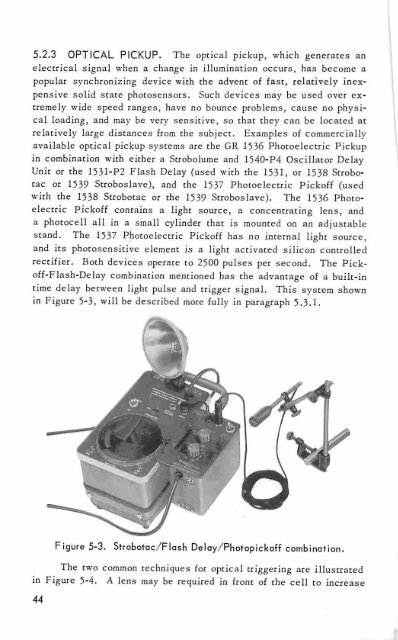
rectifier. Both devices operate to 2500 pulses per second. The Pick<strong>of</strong>f-Flash-Delay<br />
combination mentioned has the advantage <strong>of</strong> a built-in<br />
time delay between light pulse and trigger signal. This system shown<br />
in Figure 5-3, will be described more fully in paragraph 5.3.1.<br />
Figure 5-3. Strobotac/Flash Delay/Photopick<strong>of</strong>f combination.<br />
The two common techniques for optical triggering are illustrated<br />
in Figure 5-4. A lens may be required in front <strong>of</strong> the cell to increase<br />
44