Handbook of High Speed Photography - IET Labs, Inc.
Handbook of High Speed Photography - IET Labs, Inc.
Handbook of High Speed Photography - IET Labs, Inc.

Create successful ePaper yourself
Turn your PDF publications into a flip-book with our unique Google optimized e-Paper software.
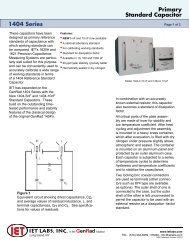
pickup is used). Figure 5-6 illustrates the operation <strong>of</strong> these pickups.<br />
The strength <strong>of</strong> the signal generated by these devices depends on the<br />
subject speed and distance from the pickup. There is strong physical<br />
attraction between the pickup and the subject. The widely available<br />
proximity device is best suited to applications where it may be per<br />
manently mounted at an accurately controlled distance from the subject.<br />
An iron patch mounted on a nonferromagnetic rotating shaft such as the<br />
one in Figure 5-6a is an example <strong>of</strong> this type <strong>of</strong> application. A variable<br />
reluctance pickup could be mounted near an iron or steel gear, whose<br />
passing teeth will generate a signal. For low speed applications, it<br />
is possible to build satisfactory pickups, such as the one in Figure<br />
5-6b, using parts from sensitive electrical relays. Commercially made<br />
proximity pickups may be obtained fromAirpax Electronics <strong>Inc</strong>orporated,<br />
Seminole Division, Fort Lauderdale, Florida or from Electro Products<br />
Laboratories, <strong>Inc</strong>., Chicago, Illinois 60648.<br />
IRON PATCH<br />
MAGNET<br />
TRIGGER<br />
SIGNAL<br />
- ROTATING<br />
_A_ PART<br />
TRIGGER SIGNAL<br />
Figure 5-6. Triggering by proximity pickups.<br />
5.2.6 ACOUSTIC TRIGGERING. The sound associated with the event<br />
to be photographed may be detected by a microphone to provide syn<br />
chronization. This type <strong>of</strong> sensing is reliable for loud noises and easy<br />
to set up, and it does not load or otherwise interfere with the subject.<br />
The separation between the microphone and the sound source may be<br />
adjusted to vary the trigger delay. This delay, approximately 0.9 milli<br />
second per foot <strong>of</strong> separation, is quite stable and is adjustable over a<br />
very wide range. An amplifier is usually required to increase the micro<br />
phone output to a usable level. (Any amplifier, for instance, a highfidelity<br />
amplifier might work.) The sound <strong>of</strong> the event must contrast<br />
sharply with any background noise to prevent spurious triggering. To<br />
effect this, the amplifier gain, normally controllable over a wide range,<br />
can be set to a level at which the noise is rejected and only the signal<br />
causes triggering. Figure 5-8 shows a typical acoustic triggering setup.<br />
To minimize the amount <strong>of</strong> fixed delay introduced into the system<br />
and to achieve maximum delay stability the microphone should be ar<br />
ranged so that positive pressure on the microphone's diaphragm causes<br />
the correct output trigger polarity. The photographer will have to deter-<br />
47