Tutorial EAGLE 4.1 -- 2nd edition - Cadsoft
Tutorial EAGLE 4.1 -- 2nd edition - Cadsoft
Tutorial EAGLE 4.1 -- 2nd edition - Cadsoft

Create successful ePaper yourself
Turn your PDF publications into a flip-book with our unique Google optimized e-Paper software.
<strong>EAGLE</strong>-<strong>Tutorial</strong> Version <strong>4.1</strong><br />
The Electrical Rule Check (ERC)<br />
If you haven’t entered the complete schematic yourself you can now load<br />
the file demo1.sch.<br />
The ERC command is used to test schematics for electrical errors.<br />
The results are warnings and error messages that are generated and written<br />
into a file which has the same file name as the drawing but the extension<br />
*.erc. This file is automatically displayed in a text editor window if messages<br />
were generated. To use the command click the ERC icon in the command<br />
toolbar.<br />
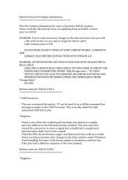
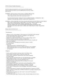
The ERC quits our sample file with two messages:<br />
WARNING: Sheet 1/1: POWER Pin IC1 VSS connected to GND<br />
WARNING: Sheet 1/1: POWER Pin IC1 VDD connected to +5V<br />
These messages inform you that the power pins are connected to other signals<br />
than expected. The power pins were named VSS or VDD in the library<br />
but are connected to GND and +5V. In our case this has be done on purpose,<br />
therefore the messages can be ignored.<br />
Please note that the ERC can only discover possible error sources. It is up to<br />
you to properly interpret the ERC messages!<br />
If you want to learn more about the ERC command, type<br />
HELP ERC ←<br />
in the command line.<br />
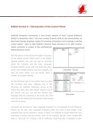
Generating a Board from a Schematic<br />
After loading a schematic from which you would like to design a board,<br />
click on the BOARD icon in the action toolbar:<br />
A board file will be generated in which the packages are positioned next to<br />
an empty board.<br />
A further description follows in the chapter Designing a PC Board.<br />
But now we want to introduce an other important command that is necessary<br />
to design schematics first.<br />
The BUS Command<br />
Load the schematic bus.sch from the /eagle/examples/tutorial directory.<br />
A schematic with a bus structure appears. A bus has to be drawn with the<br />
42