INSTRUCTION MANUAL
INSTRUCTION MANUAL
INSTRUCTION MANUAL
Create successful ePaper yourself
Turn your PDF publications into a flip-book with our unique Google optimized e-Paper software.
Decoder MX620 - MX622, MX630 - MX632 Sound Decoder MX640 - MX648 Page 33<br />
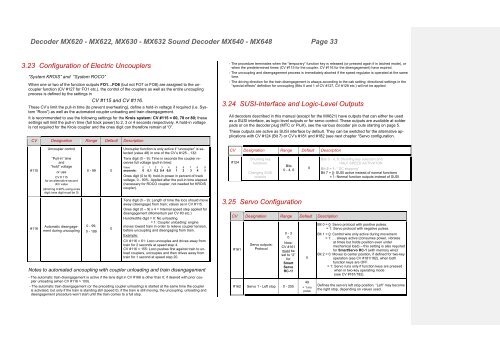
3.23 Configuration of Electric Uncouplers<br />
“System KROIS” and “System ROCO”<br />
When one or two of the function outputs FO1…FO6 (but not FO7 or FO8) are assigned to the uncoupler<br />
function (CV #127 for FO1 etc.), the control of the couplers as well as the entire uncoupling<br />
process is defined by the settings in<br />
CV #115 and CV #116.<br />
These CV’s limit the pull-in time (to prevent overheating), define a hold-in voltage if required (i.e. System<br />
“Roco”) as well as the automated coupler unloading and train disengagement.<br />
It is recommended to use the following settings for the Krois system: CV #115 = 60, 70 or 80; these<br />
settings will limit the pull-in time (full track power) to 2, 3 or 4 seconds respectively. A hold-in voltage<br />
is not required for the Krois coupler and the ones digit can therefore remain at “0”.<br />
CV Designation Range Default Description<br />
#115<br />
#116<br />
Uncoupler control<br />
“Pull-in” time<br />
and<br />
“hold” voltage<br />
or use<br />
CV # 115<br />
for an alternative second<br />
dim value<br />
(dimming 0-90% using ones<br />
digit; tens digit must be 0)<br />
Automatic disengagement<br />
during uncoupling<br />
0 - 99 0<br />
0 - 99,<br />
0 - 199<br />
0<br />
Uncoupler function is only active if “uncoupler” is selected<br />
(value 48) in one of the CV’s #125…132:<br />
Tens digit (0 – 9): Time in seconds the coupler receives<br />
full voltage (pull-in time):<br />
Value: 0 1 2 3 4 5 6 7 8 9<br />
seconds: 0 0,1 0,2 0,4 0,8 1 2 3 4 5<br />
Ones digit (0 to 9): hold-in power in percent of track<br />
voltage, 0 - 90%. Applied after the pull-in time elapsed<br />
(necessary for ROCO coupler, not needed for KROIS<br />
coupler).<br />
Tens digit (0 – 9): Length of time the loco should move<br />
away (disengage) from train; values as in CV #115.<br />
Ones digit (0 – 9) x 4 = Internal speed step applied for<br />
disengagement (Momentum per CV #3 etc.)<br />
Hundredths digit = 0: No unloading.<br />
= 1: Coupler unloading: engine<br />
moves toward train in order to relieve coupler tension,<br />
before uncoupling and disengaging from train.<br />
Example:<br />
CV #116 = 61: Loco uncouples and drives away from<br />
train for 2 seconds at speed step 4.<br />
CV #116 = 155: Loco pushes first against train to unload<br />
couplers, uncouples and then drives away from<br />
train for 1 second at speed step 20.<br />
Notes to automated uncoupling with coupler unloading and train disengagement<br />
- The automatic train disengagement is active if the tens digit in CV #166 is other than 0; if desired with prior coupler<br />
unloading (when CV #116 > 100).<br />
- The automatic train disengagement (or the preceding coupler unloading) is started at the same time the coupler<br />
is activated, but only if the train is standing still (speed 0); if the train is still moving, the uncoupling, unloading and<br />
disengagement procedure won’t start until the train comes to a full stop.<br />
- The procedure terminates when the “temporary” function key is released (or pressed again if in latched mode), or<br />
when the predetermined times (CV #115 for the coupler, CV #116 for the disengagement) have expired.<br />
- The uncoupling and disengagement process is immediately aborted if the speed regulator is operated at the same<br />
time.<br />
- The driving direction for the train disengagement is always according to the cab setting; directional settings in the<br />
“special effects” definition for uncoupling (Bits 0 and 1 of CV #127, CV #128 etc.) will not be applied.<br />
3.24 SUSI-Interface and Logic-Level Outputs<br />
All decoders described in this manual (except for the MX621) have outputs that can either be used<br />
as a SUSI interface, as logic level outputs or for servo control. These outputs are available at solder<br />
pads or on the decoder plug (MTC or PluX), see the various decoder pin outs starting on page 5.<br />
These outputs are active as SUSI interface by default. They can be switched for the alternative applications<br />
with CV #124 (Bit 7) or CV’s #181 and #182 (see next chapter “Servo configuration.<br />
CV Designation Range Default Description<br />
#124<br />
Shunting key<br />
functions:<br />
Changing SUSI<br />
outputs<br />
Bits<br />
0 - 4, 6<br />
3.25 Servo Configuration<br />
CV Designation Range Default Description<br />
#161<br />
Servo outputs:<br />
Protocol<br />
0 - 3<br />
0<br />
Note:<br />
CV #161<br />
must be<br />
set to “2”<br />
for<br />
Smart<br />
Servo<br />
RC-1!<br />
#162 Servo 1 - Left stop 0 - 255<br />
0<br />
0<br />
49<br />
= 1 ms<br />
pulse<br />
Bits 0 - 4, 6: Shunting key selection and<br />
HALF-SPEED ACTIVATON<br />
Bit 5 = 1: “ DC stopping”<br />
Bit 7 = 0: SUSI active instead of normal functions<br />
= 1: Normal function outputs instead of SUSI<br />
Bit 0 = 0: Servo protocol with positive pulses.<br />
= 1: Servo protocol with negative pulses.<br />
Bit 1 = 0: Control wire only active during movement<br />
= 1: … always active (consumes power, vibrates<br />
at times but holds position even under<br />
mechanical load) – this setting is also required<br />
for SmartServo RC-1 (with memory wire)!<br />
Bit 2 = 0: Moves to center position, if defined for two-key<br />
operation (see CV #181/182), when both<br />
function keys are OFF.<br />
= 1: Servo runs only if function keys are pressed<br />
when in two-key operating mode<br />
(see CV #181/182).<br />
Defines the servo’s left stop position. “Left” may become<br />
the right stop, depending on values used.


