INSTRUCTION MANUAL
INSTRUCTION MANUAL
INSTRUCTION MANUAL

Create successful ePaper yourself
Turn your PDF publications into a flip-book with our unique Google optimized e-Paper software.
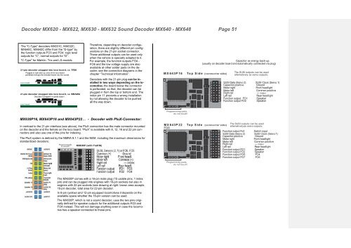
Decoder MX620 - MX622, MX630 - MX632 Sound Decoder MX640 - MX648 Page 51<br />
The "C-Type" decoders MX631C, MX632C,<br />
MX640C, MX642C differ from the "D-type" by<br />
the function outputs FO3 and FO4: logic level<br />
outputs for “C”, normal outputs for “D”.<br />
"C-Type" for Märklin. Trix and LS-models.<br />
Therefore, depending on decoder configuration,<br />
there are slightly different pin configurations<br />
on the 21-pin socket connector.<br />
These additional outputs can be used only<br />
when the vehicle is specially adapted to it.<br />
For example, the function outputs FO4 -<br />
FO6 and the low voltage supply are also<br />
available at other solder pads on the decoder;<br />
see the connection diagrams in the<br />
chapter “Technical Information”.<br />
MX643P16<br />
Capacitor as energy back-up.<br />
(usually on decoder board and automatically connected via plug)<br />
Top Side (connector side)<br />
The SUSI outputs can be used<br />
alternatively as servo outputs;<br />
Decoders with the 21-pin plug can be installed<br />
in two ways depending on the locomotive;<br />
the board below the connector<br />
is perforated, so that, the decoder can be<br />
plugged in from the top or bottom end. The<br />
index pin 11 prevents a wrong installation<br />
by not allowing the decoder to be pushed<br />
all the way down.<br />
SUSI Data (Servo 2)<br />
Capacitor positive<br />
SUSI Clock (Servo 1)<br />
Ground<br />
Motor right<br />
Front headlight<br />
Motor left<br />
Common positive<br />
Right rail --- (Index)<br />
Left rail<br />
Rear headlight<br />
Function output FO1<br />
Function output FO2<br />
Speaker<br />
Speaker<br />
MX630P16, MX643P16 and MX643P22… - Decoder with PluX-Connector:<br />
In contrast to the 21-pin interface (see above), the PluX connection has the male connector mounted<br />
on the decoder and the female on the loco board. “PluX” is available with 8, 12, 16 and 22 pin connectors<br />
and also use one of the pins for indexing.<br />
The PluX system is defined by the NMRA 9.1.1 and the NEM, including the maximum dimensions for<br />
standardized decoders.<br />
Programming pads,<br />
do not touch!<br />
MX643P22<br />
FO8<br />
Top Side (connector side)<br />
The SUSI outputs can be used<br />
alternatively as servo outputs;<br />
Function output Fo3 Switch input<br />
SUSI Data (Servo 2)<br />
Capacitor positive<br />
SUSI Clock (Servo 1)<br />
Ground<br />
Motor right<br />
Front headlight<br />
Motor left<br />
Common positive<br />
Right rail --- (Index)<br />
Left rail<br />
Rear headlight<br />
Function output FO1<br />
Function output FO 2<br />
Speaker<br />
Speaker<br />
Function output FO 5 FO4<br />
Function output FO 7 FO6<br />
Programming pads,<br />
do not touch!<br />
The MX630P comes with a 16-pin male plug (15 usable pins, 1 index<br />
pin) and can be plugged into engines with 16-pin sockets but also in<br />
engines with 22-pin sockets (see drawing at right: brown area accepts<br />
16-pin decoder, total area for 22-pin decoder.<br />
In 8-pin (yellow) and 12-pin equipped locomotives it depends on the<br />
available space whether the 16-pin version can be used.<br />
The MX630P, which is not a sound decoder, uses the two pins originally<br />
defined for speaker outputs for the additional outputs FO3 and<br />
FO4 instead. This will not damage anything even in case the locomotive<br />
has a speaker connected to those pins.