INSTRUCTION MANUAL
INSTRUCTION MANUAL
INSTRUCTION MANUAL

You also want an ePaper? Increase the reach of your titles
YUMPU automatically turns print PDFs into web optimized ePapers that Google loves.
Decoder MX620 - MX622, MX630 - MX632 Sound Decoder MX640 - MX648 Page 49<br />
Red<br />
Black<br />
Orange<br />
Blue<br />
Yellow<br />
White<br />
Gray<br />
Right rail<br />
Left rail<br />
Headlights<br />
Rear Front<br />
2 Diodes 1N4007<br />
Field coils<br />
AC-motor<br />
Most locomotives with AC motors get the power supplied by a third rail, which is of no significance<br />
as far as the motor hook-up is concerned. The above schematic is therefore valid for AC locomotives<br />
running on two or three rail track (instead of “right rail” and “left rail” think “outside rails” and “center<br />
rail”).<br />
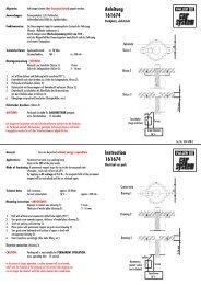
Note: many locomotive manufacturers supply field magnets that can be used in place of the motor’s<br />
field coil. Using a field magnet turns an AC motor into a DC motor, which is connected as such (see<br />
above) and can also utilize the decoders BEMF feature (BEMF does not work with AC motors).<br />
Additional hook-up for cab lighting controlled with F0 key:<br />
This is no longer of much use today; it is a remainder from a time when decoders only had two function<br />
outputs, which were used for the headlights and the cab light. Cab lights connected this way can<br />
be switched with the F0 key but in contrast to the headlights were non-directional.<br />
This is however a general schematic that can be used in cases where something is to be operated<br />
by several different function outputs, but the same outputs used independent of each other. There<br />
are 2 diodes required (type 1N4007 or equivalent) available from ZIMO or any electronic parts supply<br />
store.<br />
Blue<br />
Yellow<br />
White<br />
Headlights<br />
Rear Front<br />
2 Diodes<br />
1N4007<br />
Cab light bulb<br />
Connecting function outputs FO1, FO2, FO3, FO4…:<br />
Depending on decoder type, function outputs FO1 and higher are available on wires, solder pads or<br />
part of a connector (i.e. the MX620 offers FO1 and FO2 on solder pads, the MX630 and MX632 on<br />
wires with higher outputs on solder pads) and can be connected in the same fashion as headlights.<br />
For mapping the outputs to function keys, see chapter 5; the function outputs FO1 and FO2 are<br />
mapped by default with function keys F1 and F2.<br />
Also see note on MX632 below!<br />
Red<br />
Black<br />
blue<br />
Yellow<br />
White<br />
Right rail<br />
Left rail<br />
Headlights<br />
Rear Front<br />
Rotor<br />
M<br />
E.g.<br />
Cab light<br />
Using logic level outputs:<br />
ZIMO decoders also have so called logic level outputs in addition to the normal function outputs, to<br />
which current consuming devices may not be connected directly. Use a ZIMO M4000A amplifier or<br />
similar transistor switching device, when connecting logic level outputs with a load.<br />
Some logic level outputs are used alternatively for the “SUSI-CLOCK” and SUSI-DATA” connections<br />
and can be switched back to logic level outputs when setting CV #124 Bit 7 = 1 (if SUSI is not required).<br />
Furthermore, the same pins can be used for servo control (activated with CV’s #181 & 182).<br />
NOTE MX632: The logic level outputs FO5 and FO6 of the MX632 are identical in their function as<br />
the amplified outputs FO5 and FO6 (not FO7 and FO8 as was first announced); however, neither<br />
the amplified outputs FO5/FO6 nor the logic level outputs FO5/FO6 are functional, if they are<br />
defined for “SUSI” (CV #124, Bit 7) or servo control (CV’s #181, 182) are activated!!<br />
The brown lead of an amplifier module M4000Z is connected with the relevant logic level output<br />
solder pad of the decoder.<br />
Brow n<br />
B lue (+)<br />
M4000Z G reen (-)<br />
Connect to SUSI-CLOCK or SUSI-DATA solder<br />
pads of the MX620, convert the outputs to function 2 x black<br />
outputs with CV #124, Bit 7.<br />
To track<br />
e.g.<br />
Smoke generator,<br />
uncoupler etc.<br />
Connecting DIETZ sound modules without “SUSI” / “virtual cam sensor”<br />
See Dietz instruction manual regarding the installation and connection of their sound modules to a<br />
ZIMO decoder.<br />
For a good acoustic impression of steam engines, it is important that the chuffs are synchronized to<br />
wheel revolutions. Therefore a cam sensor should be installed and connected to the sound module<br />
(reed switch, optical or hall-effect sensor), which sends exactly 2 or 4 pulses to the module (depending<br />
on loco type).<br />
Sound modules can usually generate their own chuff rate based on speed information (e.g. coming<br />
through the SUSI interface from a decoder), if no cam sensor can be installed or installation proves<br />
too difficult. The result is often poor with a chuff rate that is too fast at low speeds (the SUSI protocol<br />
is not precise enough in that respect).<br />
To improve this situation, ZIMO decoders come with a “virtual cam sensor”. Function output FO4<br />
is converted to a “virtual cam sensor” function with the help of CV #133 and connected with the cam<br />
sensor input of the sound module (e.g. Dietz, reed switch input); this in addition to SUSI or other<br />
connections.<br />
The virtual cam sensor is of course not capable of synchronizing chuff rates to wheel positions but<br />
rather to wheel speed, which is of little difference to the viewer.<br />
The chuff rate of the “virtual cam sensor” can be defined per wheel revolution with CV #267 and CV<br />
#354; consult the CV table in ZIMO sound chapter.<br />
Solder pad FO1