INSTRUCTION MANUAL
INSTRUCTION MANUAL
INSTRUCTION MANUAL

You also want an ePaper? Increase the reach of your titles
YUMPU automatically turns print PDFs into web optimized ePapers that Google loves.
Decoder MX620 - MX622, MX630 - MX632 Sound Decoder MX640 - MX648 Page 53<br />
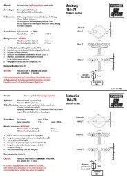
MX640… – Complete Schematic including Sound Connections<br />
MX642, MX644, MX645 …<br />
More recent sound decoder versions are to be wired the same<br />
way, except that<br />
- ground, switch input and common power are on solder<br />
pads on the top side or common power from the blue<br />
wire and<br />
- only 2 LED outputs (MX642) or none are available,<br />
which can be used alternatively to the SUSI pads on<br />
the top side solder pads.<br />
Also see the decoder schematics on the first pages of this manual.<br />
Connecting speaker, cam sensor:<br />
In order to operate the MX640 as a sound decoder, the following items<br />
must/may be connected:<br />
- mandatory – SPEAKER – Any 8-ohm speaker or two 4 Ohm speakers<br />
connected in series can be used. Speaker with higher impedance<br />
are also allowed but will result in reduced volume.<br />
An additional tweeter (also 8 ohms or higher) can be connected, if desired;<br />
the connection should be made via a bipolar capacitor (10 uF<br />
bipolar for 2 kHz frequency).<br />
- optional – CAM SENSOR – Normally, ZIMO decoders are programmed<br />
for the “virtual cam sensor”, which can be fine-tuned with<br />
CV #267 and CV #354. If a real cam sensor is to be used, the settings<br />
of CV #267 must be changed to 0 or 1 depending whether each pulse<br />
or every second pulse should trigger a chuff beat. See chapter 6!<br />
Mechanical contacts, Reed switches, optical switches and Hall Effect<br />
switches are suitable as cam sensors.