INSTRUCTION MANUAL
INSTRUCTION MANUAL
INSTRUCTION MANUAL
Create successful ePaper yourself
Turn your PDF publications into a flip-book with our unique Google optimized e-Paper software.
Decoder MX620 - MX622, MX630 - MX632 Sound Decoder MX640 - MX648 Page 61<br />
Now enter the ones digit of the same CV (for example: for CV 123 enter 03) and operate the direction<br />
switch again.<br />
The headlight briefly flashes 3 times.<br />
Enter the hundreds and tens digit in the central unit for the value you want to program and operate<br />
the direction switch.<br />
The headlight briefly flashes 4 times.<br />
Now enter the ones digit of the value and operate the direction switch again.<br />
Again, the headlight flashes once indicating that you can program the next CV or end the programming<br />
by turning track power off.<br />
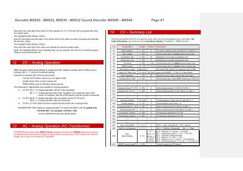
12 DC – Analog Operation<br />
ZIMO decoders switch automatically to analog when DC voltage is present and CV #29 is set accordingly<br />
(Bit 2 = 1, which is the default setting).<br />
Operation is possible with various power packs:<br />
– “normal” DC throttles, with poor or no ripple control<br />
– smooth power from a power supply unit<br />
– PWM throttles such as the Roco analog mouse.<br />
The following CV adjustments are possible for analog operation:<br />
CV #14, Bit 7 = 0: Analog operation without motor regulation<br />
Bit 7 = 1: Analog operation with motor regulation (is of particular value with\<br />
sound; for example: that the chuff frequency fits the wheel movements)<br />
CV #14, Bit 6 = 0: Analog operation with momentum as per CV #3 and 4.<br />
Bit 6 = 1: Analog operation without momentum.<br />
CV #13, CV #14: Select function outputs that should be ON in analog mode.<br />
SUGGESTION: With extensive analog operation it is recommended to use the update lock<br />
CV #144, Bit 7, for example: CV #144 = 128,<br />
to avoid interference and poor performance!<br />
13 AC – Analog Operation (AC-Transformer)<br />
ATTENTION: Decoders of the MX621 family (miniature decoder) and MX640 (older sound decoders)<br />
do not have the dielectric strength to cope with the surge pulses (>30V) required for direction<br />
change, as is used in the classic AC operation!<br />
14 CV – Summery List<br />
This list summarizes all CV's in numerical order, with very short descriptions (as a reminder). Detailed<br />
information can be found in the preceding chapters ("Configure", "ZIMO Sound").<br />
CV Designation Range Default Description<br />
#1 Short address 1 – 127 3 The “short” address; active when Bit 5 in CV #29 is 0.<br />
#2 Start voltage 1 - 255 1 Internal speed step for lowest external speed step.<br />
#3 Acceleration rate 0 - 255 (2) Multiplied by 0.9 equals’ acceleration time.<br />
#4 Deceleration rate 0 - 255 (1) Multiplied by 0.9 equals’ deceleration time.<br />
#5 Top speed 0 - 255 1 (=255) Internal speed step for highest external speed step.<br />
#6 Medium speed 32 - 128 1 (=1/3 # 5) Internal speed step for medium external speed step.<br />
#7 SW-Version number Read-only - The current SW number; for subversion see CV #65.<br />
#8 Manuf.-ID, Reset, Set 0, 8, Set # 145 (ZIMO) given by the NMRA; CV #8 = 8 Hard Reset.<br />
#9 Motor regulation. 1 - 255 55 Sample time (tens digit), sample rate (ones digit)<br />
#10 Compensation-Cutoff 0 - 252 0 Internal speed step, where BEMF intensity per CV#113.<br />
#11 ------<br />
#12 ------<br />
#13 Analog functions F1 - F8 0 - 255 0 Select analog functions F1 (Bit 0), F2 (Bit 1)...<br />
#14 Analog funct. F0, F9 … 0 - 255 0 Select analog functions, F0 forw (Bit 0), rev (Bit 1)...<br />
#15 ------<br />
#16 ------<br />
#17,18 Extended address 128 -10239 0 The long address. Active when CV #29, Bit 5 = 1.<br />
#19 Consist address 0 - 127 0 Consist address active when > 0.<br />
#21 Consist function F1 - F8 0 - 255 0 Select consist functions F1 (Bit 0), F2 (Bit 1)….<br />
#22 Consist function F0 0 - 3 0 Select consist function F0 forw (Bit 0), rev (Bit 1).<br />
#23 Acceleration variation 0 - 255 0 For temporary adjustment to CV #3<br />
#24 Deceleration variation 0 - 255 0 For temporary adjustment to CV #4<br />
#25 ------<br />
#26 ------<br />
#27 Asym. Stop (ABC) 0, 1, 2, 3 0 Bit 0 = 1: Stop, with right rail Bit 1: left rail<br />
#28 RailCom Configuration 0, 1, 2, 3 3 Bit 0 = 1: RailCom (Broadcast) Bit 1 = 1: Data<br />
14 = Bit 0 – Direction: 0 = normal, 1 = reversed<br />
#29<br />
DCC<br />
0000 1110 Bit 1 – Speed step system: 0 = 14, 1 = 28, 128<br />
Basic Settings 0 - 63<br />
Bit 2 – Automatic analog operation<br />
with Bits 1, 2,<br />
3 (28 SS, Bit 3 – RailCom: 0 = OFF, 1 = ON<br />
Analog, Bit 4 – Speed curve: 0 = 3-point, 1 = free definition<br />
RailCom) Bit 5 – Short/long address: 0 = CV #1, 1 = CV‘s #17,18<br />
#33 NMRA Function map F0 0 - 255 1 Function mapping for F0 forward


