INSTRUCTION MANUAL
INSTRUCTION MANUAL
INSTRUCTION MANUAL

Create successful ePaper yourself
Turn your PDF publications into a flip-book with our unique Google optimized e-Paper software.
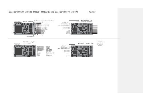
Decoder MX620 - MX622, MX630 - MX632 Sound Decoder MX640 - MX648 Page 7<br />
Switch input 1<br />
Switch input 2<br />
Programming pads,<br />
do not touch !<br />
MX640 Top Side<br />
Function output FO4<br />
5 V, 200 mA power supply for small servos (i.e. SmartServo) MX640 Bottom Side<br />
Function output FO3<br />
FO8 FO9 (= where wires are soldered to)<br />
LED (10 mA) - or<br />
purple-purple<br />
logic level outputs<br />
Speaker - Speaker<br />
AT T ENT IO N: connect<br />
FA 5<br />
brown<br />
Function output FO2<br />
other side to Ground ! FA 6<br />
green<br />
white<br />
Function output FO1<br />
Front headlight<br />
(which is opposite to “normal” FO’s) FA 7<br />
yellow<br />
F unction outputs F O 4<br />
Rear headlight<br />
blue (+)<br />
F unction output F O 3<br />
gray<br />
Common positive<br />
orange<br />
Motor left<br />
G round<br />
black<br />
Motor right<br />
SUSI Data<br />
red<br />
Left rail<br />
SUSI Clock<br />
Right rail<br />
SUSI Positive<br />
Switch input<br />
Switch input 1<br />
Switch inpout 2<br />
Programming pads,<br />
do not touch !<br />
MX640D, C Top Side<br />
(= with 21-pin plug !)<br />
5 V, 200 mA, for small servo<br />
+ 5 V, 200 mA max.<br />
Function output FO3<br />
Function output FO2<br />
Function output FO1<br />
Common positive<br />
n.a.<br />
Motor left<br />
Motor right<br />
Ground<br />
Left rail<br />
Right rail<br />
Index pin<br />
Speaker<br />
Speaker<br />
Front headlight<br />
Rear headlight<br />
SUSI Data<br />
SUSI Clock<br />
Function output FO4<br />
n.a.<br />
n.a.<br />
Switch input 1<br />
LED (10 mA) - or<br />
logic level outputs<br />
FO5<br />
AT T ENT IO N: connect<br />
other side to Ground ! FO6<br />
(which is opposite to “normal” FO’s) FO7<br />
F unction output F O 4<br />
F unction output F O 3<br />
G round<br />
SUSI Data<br />
SUSI Clock<br />
SUSI Positive<br />
FO8 FO9<br />
MX640D, C<br />
Bottom Side<br />
ATTENTION:<br />
The decoder can be<br />
plugged in from either<br />
side, depending on the<br />
circuit board in the<br />
locomotive.