Part I - IPA SA
Part I - IPA SA
Part I - IPA SA

You also want an ePaper? Increase the reach of your titles
YUMPU automatically turns print PDFs into web optimized ePapers that Google loves.
REVISTA ROMÂNĂ DE AUTOMATICĂ<br />
19<br />
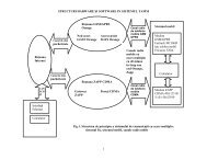
♦ Local or remote automatically stoppingdamage/normal;<br />
♦ The control of the motor driving the<br />
mechanical limitation of the directing<br />
apparatus;<br />
♦ The electro pump control to keep the<br />
nitrogen’s pressure;<br />
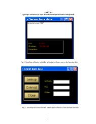
Fig 1. Interface operator-Remote control<br />
3.1.2. The system realizes the following<br />
protections:<br />
♦ Maximal voltage protection with<br />
instantaneous effect;<br />
♦ Maximal current protection with timing<br />
effect;<br />
♦ Protection against away running with<br />
instantaneous effect;<br />
♦ Protection against the motor rate<br />
running, with timing effect;<br />
The equipment acquires, processes, and<br />
transmits to the central computer, the<br />
following information:<br />
♦ The running rate of the hydro mechanic<br />
equipment –<br />
“Manually/Rest/Automatically”;<br />
♦ The key setting the hydromechanic<br />
equipment running has the position:<br />
local control/remote control;<br />
♦ The supply is : basis source/ store<br />
source;<br />
♦ The position of the supplying self –<br />
action switch: basis source/switched-in<br />
store source/released store source;<br />
♦ If exist the command: Opening/Closing<br />
of tilting gates;<br />
♦ The position of the motor supplying<br />
switch : left/right for opening/closing, is<br />
switched-in/ released;<br />
♦ Supplying voltage-from basis source/store<br />
source, on the phase : R/S/T;<br />
♦ The current consumed by the left/right<br />
motor on the phase: R/S/T;<br />
♦ The tilting gate is on the sill;<br />
♦ The position of the tilting gate: open/close;<br />
♦ The electric break of the driving mechanism:<br />
left/right, supplied/ unsupplied, running/no<br />
running;<br />
♦ The manually driving mechanism: left/right:<br />
connected/unconnected;<br />
♦ The evacuated debit (is a effective value);<br />
♦ The temperature into the control and<br />
supplying bloc (is a effective value);<br />
3.1.3. The system allows the following<br />
signaling<br />
• If run the protection of the automatic<br />
switch supplying the equipments from:<br />
basis source/store source, the motor in<br />
left/right for opening/closing driving;<br />
• Overloading left/right;<br />
• Unloading left/right;<br />
• PLC-damage;<br />
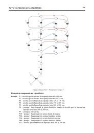
Fig 2. The system’s structure