Operator and Installation Manual Tron AIS TR-8000.pdf - Jotron
Operator and Installation Manual Tron AIS TR-8000.pdf - Jotron
Operator and Installation Manual Tron AIS TR-8000.pdf - Jotron
You also want an ePaper? Increase the reach of your titles
YUMPU automatically turns print PDFs into web optimized ePapers that Google loves.
18 List of Figures<br />
Figure 7-1 Transponder Unit, exploded view. Opening of outer Lid .................................................................. 39<br />
Figure 7-2 Desktop mounted Display Unit .......................................................................................................... 40<br />
Figure 7-3 Roof mounted Display Unit ................................................................................................................ 41<br />
Figure 7-4 Flush mounted Display Unit, exploded view. .................................................................................... 42<br />
Figure 7-5 Horizontal separation distance........................................................................................................... 43<br />
Figure 7-6 Vertical separation <strong>and</strong> distance from mast or other object of metal. For best isolation between<br />
antennas, place directly underneath with no horizontal separation. ........................................................................ 43<br />
Figure 7-7 Connection cable for interconnection between the Transponder <strong>and</strong> the Display Unit ................... 48<br />
Figure 7-8 Block diagram of typical connections ................................................................................................. 49<br />
Figure 7-9 Transponder with lid removed, lid screws highlighted ...................................................................... 50<br />
Figure 7-10: Typical connections to a <strong>TR</strong>-8000 transponder, dashed lines shows options ................................. 51<br />
Figure 7-11: Label inside transponder with corresponding table showing details about each connection. It is<br />
coloured to differentiate sensors, display/pilot, alarm <strong>and</strong> DGNSS beacon interface ............................................... 52<br />
Figure 7-12 External display connections ............................................................................................................ 55<br />
Figure 7-13 Ethernet RJ45 connector .................................................................................................................. 55<br />
Figure 7-14 Pilot plug with cable ......................................................................................................................... 56<br />
Figure 7-15 AMP 206486-1 (Pilot Plug) pinout ................................................................................................... 56<br />
Figure 7-16 Typical Alarm connection ................................................................................................................ 57<br />
Figure 7-17 Partno.: 86870, Pilot plug cable, Display Unit .................................................................................. 61<br />
Figure 7-18 Partno.: 86581, Power cable, Display Unit ....................................................................................... 61<br />
Figure 7-19 AMP 206486-1 Pinout ...................................................................................................................... 61<br />
Figure 7-20 Ethernet RJ45 connector .................................................................................................................. 62<br />
Figure 9-1 Typical Alarm connection ................................................................................................................... 81<br />
Figure 9-2 Pilot port connection, <strong>TR</strong>-8000 Transponder unit .............................................................................. 86<br />
Figure 9-3 Pilot port connection, <strong>TR</strong>-8000 Display unit (rear ) ............................................................................ 86<br />
Figure 9-4 Pilot port cable, Display unit .............................................................................................................. 86<br />
Figure 9-5 Pilot port cable, Transponder unit ..................................................................................................... 86<br />
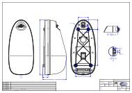
Figure 13-1 <strong>TR</strong>-8000 Transponder Unit- mechanical dimensions ..................................................................... 102<br />
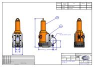
Figure 13-2 <strong>TR</strong>-8000 Display Unit- Mechanical Dimensions .............................................................................. 103<br />
Figure 13-3 <strong>TR</strong>-8000 Display Unit - Flush Mount Cutout dimensions................................................................ 104<br />
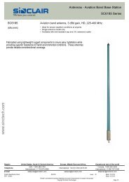
Figure 13-5 Procom CXL 2-1 VHF Antenna datasheet ....................................................................................... 106<br />
Figure 13-6 Procom GPS4 Antenna datasheet .................................................................................................. 107<br />
Figure 13-7 Sanav SA-200 GPS Antenna ............................................................................................................ 108<br />
<strong>TR</strong>-8000 <strong>Operator</strong> <strong>and</strong> <strong>Installation</strong> <strong>Manual</strong> 118


