

Operator and Installation Manual Tron AIS TR-8000.pdf - Jotron
Operator and Installation Manual Tron AIS TR-8000.pdf - Jotron
Operator and Installation Manual Tron AIS TR-8000.pdf - Jotron

You also want an ePaper? Increase the reach of your titles
YUMPU automatically turns print PDFs into web optimized ePapers that Google loves.
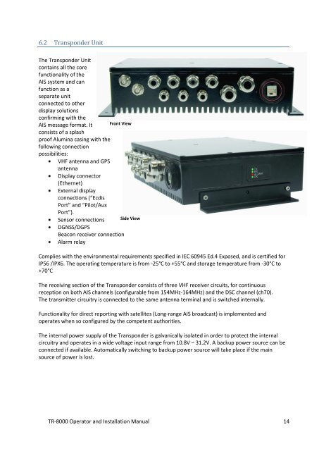
6.2 Transponder Unit<br />
The Transponder Unit<br />
contains all the core<br />
functionality of the<br />
<strong>AIS</strong> system <strong>and</strong> can<br />
function as a<br />
separate unit<br />
connected to other<br />
display solutions<br />
confirming with the<br />
<strong>AIS</strong> message format. It<br />
consists of a splash<br />
proof Alumina casing with the<br />
following connection<br />
possibilities:<br />
VHF antenna <strong>and</strong> GPS<br />
antenna<br />
Display connector<br />
(Ethernet)<br />
External display<br />
connections (“Ecdis<br />
Port” <strong>and</strong> “Pilot/Aux<br />
Port”).<br />
Sensor connections<br />
DGNSS/DGPS<br />
Beacon receiver connection<br />
Alarm relay<br />
Front View<br />
Side View<br />
Complies with the environmental requirements specified in IEC 60945 Ed.4 Exposed, <strong>and</strong> is certified for<br />
IP56 /IPX6. The operating temperature is from -25°C to +55°C <strong>and</strong> storage temperature from -30°C to<br />
+70°C<br />
The receiving section of the Transponder consists of three VHF receiver circuits, for continuous<br />
reception on both <strong>AIS</strong> channels (configurable from 154MHz-164MHz) <strong>and</strong> the DSC channel (ch70).<br />
The transmitter circuitry is connected to the same antenna terminal <strong>and</strong> is switched internally.<br />
Functionality for direct reporting with satellites (Long-range <strong>AIS</strong> broadcast) is implemented <strong>and</strong><br />
operates when so configured by the competent authorities.<br />
The internal power supply of the Transponder is galvanically isolated in order to protect the internal<br />
circuitry <strong>and</strong> operates in a wide voltage input range from 10.8V – 31.2V. A backup power source can be<br />
connected if available. Automatically switching to backup power source will take place if the main<br />
source of power is lost.<br />
<strong>TR</strong>-8000 <strong>Operator</strong> <strong>and</strong> <strong>Installation</strong> <strong>Manual</strong> 14


