- Page 2 and 3: Table of Contents 1 Revision Histor
- Page 4 and 5: 8.3.1.2 Label in transponder with c
- Page 6 and 7: 1 Revision History Revision no. By
- Page 8 and 9: 3 Introduction 3.1 Safety Instructi
- Page 10 and 11: 4 Operation general introduction Th
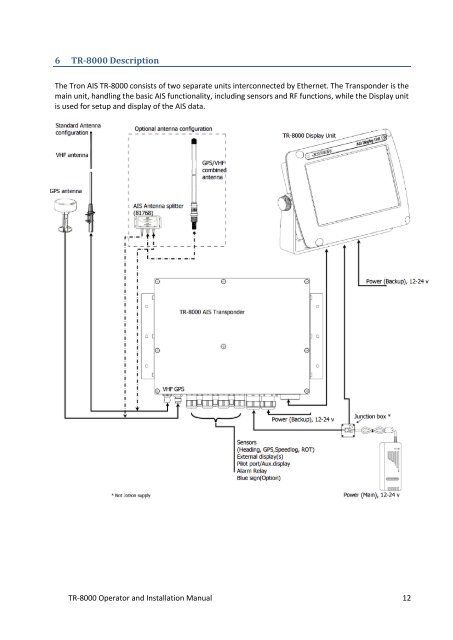
- Page 14 and 15: 6.2 Transponder Unit The Transponde
- Page 16 and 17: 6.2.5 External Display (Ethernet) C
- Page 18 and 19: 7 Operational description The opera
- Page 20 and 21: 7.2 Display Unit menu system. Statu
- Page 22 and 23: 7.2.4 Important Buttons shown in di
- Page 24 and 25: 7.2.6 Ship List The display unit re
- Page 26 and 27: 7.2.7 Graphical View The graphical
- Page 28 and 29: 7.3 Voyage Settings Red square show
- Page 30 and 31: 7.3.2 Destination The destination o
- Page 32 and 33: 7.3.6 Draught The Draught parameter
- Page 34 and 35: 7.4.2 Popup when received message E
- Page 36 and 37: 7.4.4.1 Message recipients “From
- Page 38 and 39: 7.5 Display Settings Red square sho
- Page 40 and 41: 8.1.2 Display Unit The display unit
- Page 42 and 43: 8.1.2.3 Flush/ Panel Mounting Figur
- Page 44 and 45: 8.1.3.1 GPS Antenna When selecting
- Page 46 and 47: 8.1.3.2 VHF Antenna When individual
- Page 48 and 49: 8.2.2 VHF antenna The table below s
- Page 50 and 51: 8.3.1 Transponder In order to conne
- Page 52 and 53: 8.3.1.2 Label in transponder with c
- Page 54 and 55: 8.3.1.4 Sensor connections Sensors
- Page 56 and 57: 8.3.1.6 Pilot / Aux. Display connec
- Page 58 and 59: 8.3.1.8 Detailed description of con
- Page 60 and 61: 8.3.2 Display Unit: The TR-8000 Dis
- Page 62 and 63:
Transponder (RJ45): Figure 8-20 Eth
- Page 64 and 65:
- Not subject to target loss due to
- Page 66 and 67:
10.1.1.1 Type of Vessel Select Type
- Page 68 and 69:
10.1.2 Display Settings Red square
- Page 70 and 71:
10.1.3.2 View Regions It is possibl
- Page 72 and 73:
10.1.3.3.1 Change Channel NOTE! BE
- Page 74 and 75:
10.1.3.3.3 Output Power The button
- Page 76 and 77:
10.1.3.3.5.1 Illegal Coordinates Ex
- Page 78 and 79:
The internal Alarm is triggered if
- Page 80 and 81:
032 Heading lost/invalid External h
- Page 82 and 83:
10.1.4 Indicators Red square shows
- Page 84 and 85:
10.2.1.1 Display/ Transponder IP NO
- Page 86 and 87:
10.2.1.3 Aux. Display/Pilot Port Re
- Page 88 and 89:
10.2.1.5 Priorities From this menu
- Page 90 and 91:
10.2.2 VHF link/Long Range Red squa
- Page 92 and 93:
10.2.2.5 Test Communication The Com
- Page 94 and 95:
10.2.4 Internal GPS Red square show
- Page 96 and 97:
10.2.6 Self Test Red square shows b
- Page 98 and 99:
10.2.8 Current position Red square
- Page 100 and 101:
12 List of VHF Channels Channel Fre
- Page 102 and 103:
14 Outline Drawings 14.1 TR-8000 Tr
- Page 104 and 105:
14.3 TR-8000 Display Unit, Flush/Pa
- Page 106 and 107:
14.5 Procom CXL 2-1LW/h Maritime VH
- Page 108 and 109:
14.7 SANAV - GPS Marine Antenna Fig
- Page 110 and 111:
15 Abbreviations and Definitions AC
- Page 112 and 113:
RCC RF RMS ROT RNG RX SAR S/N SOG S
- Page 114 and 115:
16 Service Procedure WARRANTY CLAIM
- Page 116 and 117:
16.2 Trouble Description Form For b
- Page 118 and 119:
18 List of Figures Figure 7-1 Trans