

Operator and Installation Manual Tron AIS TR-8000.pdf - Jotron
Operator and Installation Manual Tron AIS TR-8000.pdf - Jotron
Operator and Installation Manual Tron AIS TR-8000.pdf - Jotron

Create successful ePaper yourself
Turn your PDF publications into a flip-book with our unique Google optimized e-Paper software.
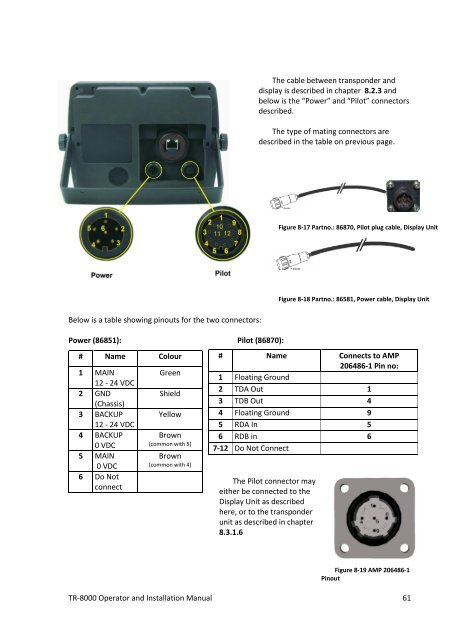
The cable between transponder <strong>and</strong><br />
display is described in chapter 8.2.3 <strong>and</strong><br />
below is the “Power” <strong>and</strong> “Pilot” connectors<br />
described.<br />
The type of mating connectors are<br />
described in the table on previous page.<br />
Figure 8-17 Partno.: 86870, Pilot plug cable, Display Unit<br />
Figure 8-18 Partno.: 86581, Power cable, Display Unit<br />
Below is a table showing pinouts for the two connectors:<br />
Power (86851): Pilot (86870):<br />
# Name Colour<br />
1 MAIN<br />
12 - 24 VDC<br />
2 GND<br />
(Chassis)<br />
3 BACKUP<br />
12 - 24 VDC<br />
4 BACKUP<br />
0 VDC<br />
5 MAIN<br />
0 VDC<br />
6 Do Not<br />
connect<br />
Green<br />
Shield<br />
Yellow<br />
Brown<br />
(common with 5)<br />
Brown<br />
(common with 4)<br />
# Name Connects to AMP<br />
206486-1 Pin no:<br />
1 Floating Ground<br />
2 TDA Out 1<br />
3 TDB Out 4<br />
4 Floating Ground 9<br />
5 RDA In 5<br />
6 RDB in 6<br />
7-12 Do Not Connect<br />
The Pilot connector may<br />
either be connected to the<br />
Display Unit as described<br />
here, or to the transponder<br />
unit as described in chapter<br />
8.3.1.6<br />
Figure 8-19 AMP 206486-1<br />
Pinout<br />
<strong>TR</strong>-8000 <strong>Operator</strong> <strong>and</strong> <strong>Installation</strong> <strong>Manual</strong> 61


