

Operator and Installation Manual Tron AIS TR-8000.pdf - Jotron
Operator and Installation Manual Tron AIS TR-8000.pdf - Jotron
Operator and Installation Manual Tron AIS TR-8000.pdf - Jotron

You also want an ePaper? Increase the reach of your titles
YUMPU automatically turns print PDFs into web optimized ePapers that Google loves.
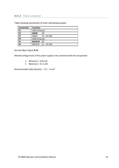
8.3.1.3 Power connection<br />
Table showing connection of main <strong>and</strong> backup power<br />
Connection Function<br />
P1<br />
GND (Chassis)<br />
P2 MAIN 0V<br />
P3 MAIN 12 - 24 VDC<br />
P4<br />
GND (Chassis)<br />
P5 BACKUP 0V<br />
P6<br />
BACKUP 12 – 24 VDC<br />
See also figure Figure 8-10<br />
Allowed voltage levels of the power supply to be connected with the transponder:<br />
Minimum = 10.8 volt<br />
Maximum = 31.2 volt<br />
Recommended cable diameter: 2.5 – 4 mm 2<br />
<strong>TR</strong>-8000 <strong>Operator</strong> <strong>and</strong> <strong>Installation</strong> <strong>Manual</strong> 53


