

Operator and Installation Manual Tron AIS TR-8000.pdf - Jotron
Operator and Installation Manual Tron AIS TR-8000.pdf - Jotron
Operator and Installation Manual Tron AIS TR-8000.pdf - Jotron

Create successful ePaper yourself
Turn your PDF publications into a flip-book with our unique Google optimized e-Paper software.
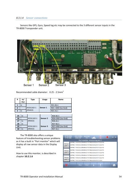
8.3.1.4 Sensor connections<br />
Sensors like GPS, Gyro, Speed log etc may be connected to the 3 different sensor inputs in the<br />
<strong>TR</strong>-8000 Transponder unit.<br />
Recommended cable diameter: 0.25 - 2.5mm 2<br />
# In/<br />
Out<br />
Type Usage Name<br />
1 In<br />
RD1-B(+)<br />
2 IEC61162-1 Sensor 1 RD1 -GND (Iso Gnd)<br />
3 In (RS422)<br />
RD1-A(-)<br />
25 In<br />
RD6-B(+)<br />
26 IEC61162-1 Sensor 2 RD6-GND (Iso Gnd)<br />
27 In (RS422)<br />
RD6-A(-)<br />
28 In<br />
RD7-B(+)<br />
29 IEC61162-1 Sensor 3 RD7-GND (Iso Gnd)<br />
30 In (RS422)<br />
RD7-A(-)<br />
The <strong>TR</strong>-8000 also offers a unique<br />
feature of troubleshooting sensor problems<br />
as it has a built in “Port monitor” which will<br />
display all raw sensor data in the Display<br />
Unit.<br />
How to use this monitor, is described in<br />
chapter 10.2.1.6<br />
<strong>TR</strong>-8000 <strong>Operator</strong> <strong>and</strong> <strong>Installation</strong> <strong>Manual</strong> 54


