

Operator and Installation Manual Tron AIS TR-8000.pdf - Jotron
Operator and Installation Manual Tron AIS TR-8000.pdf - Jotron
Operator and Installation Manual Tron AIS TR-8000.pdf - Jotron

Create successful ePaper yourself
Turn your PDF publications into a flip-book with our unique Google optimized e-Paper software.
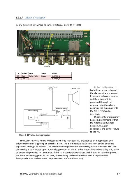
8.3.1.7 Alarm Connection<br />
Below picture shows where to connect external alarm to <strong>TR</strong>-8000<br />
# In/Out Type Usage Name<br />
37 Out Relay (NC) Alarm ALARM_A<br />
38 Out ALARM_B<br />
Figure 8-16 Typical Alarm connection<br />
In this configuration,<br />
both the external relay <strong>and</strong><br />
the alarm unit are powered<br />
from external power source,<br />
<strong>and</strong> the alarm unit is<br />
grounded through the<br />
external relay if an alarm<br />
occurs or the main power to<br />
the <strong>AIS</strong> is removed or<br />
defective.<br />
Other configurations may<br />
be used, but remember that<br />
the Alarm must function<br />
both on <strong>AIS</strong> Alarm<br />
conditions, <strong>and</strong> power failure<br />
to the <strong>AIS</strong>.<br />
The Alarm relay is a normally closed earth free relay contact, provided as an independent <strong>and</strong><br />
simple method for triggering an external alarm. The alarm relay is active in case of power off <strong>and</strong> is<br />
capable of driving a 2A current. The maximum voltage over the alarm relay must not exceed 48V. The<br />
alarm relay is deactivated upon acknowledgment of an alarm, either internally on the display unit, or by<br />
an externally provided ACK sentence. If the Transponder power is lost, <strong>and</strong> the Alarm relay has power,<br />
the alarm will be triggered. In this case, the only way to deactivate the Alarm is to power the<br />
Transponder unit or disconnect the power source of the Alarm relay.<br />
<strong>TR</strong>-8000 <strong>Operator</strong> <strong>and</strong> <strong>Installation</strong> <strong>Manual</strong> 57


