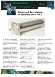
User Manual - JVL Industri Elektronik A/S
User Manual - JVL Industri Elektronik A/S
User Manual - JVL Industri Elektronik A/S

You also want an ePaper? Increase the reach of your titles
YUMPU automatically turns print PDFs into web optimized ePapers that Google loves.
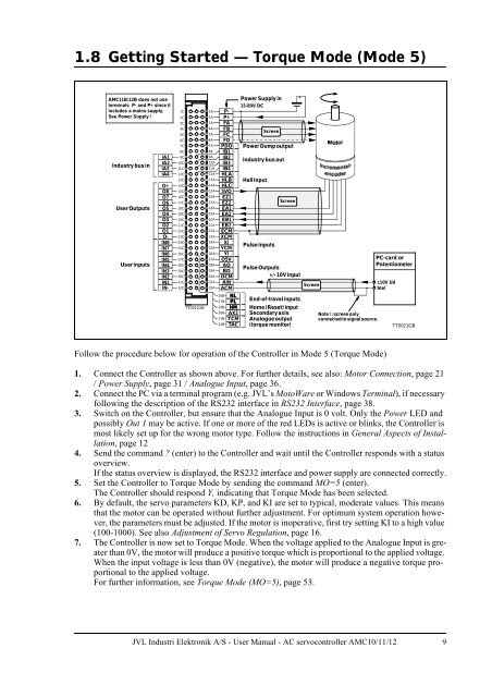
1.8 Getting Started — Torque Mode (Mode 5)<br />
AMC11B/12B does not use<br />
terminals P- and P+ since it<br />
includes a mains supply.<br />
See Power Supply !<br />
Industry busin<br />
<strong>User</strong> Outputs<br />
<strong>User</strong> Inputs<br />
IA1<br />
IA2<br />
IA3<br />
IA4<br />
O+<br />
O8<br />
O7<br />
O6<br />
O5<br />
O4<br />
O3<br />
O2<br />
O1<br />
O-<br />
IN8<br />
IN7<br />
IN6<br />
IN5<br />
IN4<br />
IN3<br />
IN2<br />
IN1<br />
IN-<br />
1C<br />
2C<br />
3C<br />
4C<br />
5C<br />
6C<br />
7C<br />
8C<br />
9C<br />
10C<br />
11C<br />
12C<br />
13C<br />
14C<br />
15C<br />
16C<br />
17C<br />
18C<br />
19C<br />
20C<br />
21C<br />
22C<br />
23C<br />
24C<br />
25C<br />
26C<br />
27C<br />
28C<br />
29C<br />
30C<br />
31C<br />
32C<br />
TT0021GB<br />
1A P-<br />
2A P+<br />
3A FA<br />
4A FB<br />
5A FC<br />
6A FD<br />
7A PDO<br />
8A IB1<br />
9A IB2<br />
10A IB3<br />
11A IB4<br />
12A HLA<br />
13A HLB<br />
14A HLC<br />
15A 5VO<br />
16A EZ1<br />
17A EZ2<br />
18A EA1<br />
19A EA2<br />
20A EB1<br />
21A EB2<br />
22A ECM<br />
23A XCM<br />
24A XI<br />
25A YCM<br />
26A YI<br />
27A O5V<br />
28A AO<br />
29A BO<br />
30A OCM<br />
31A AIN<br />
32A ACM<br />
26B<br />
NL<br />
27B<br />
PL<br />
28B<br />
HM<br />
30B AX2<br />
31B TCM<br />
32B TAC<br />
Power Supply in<br />
15-80V DC<br />
Power Dump output<br />
Industrybus out<br />
Hall Input<br />
Screen<br />
PulseInputs<br />
Screen<br />
PulseOutputs<br />
+/-10V Input<br />
End-of-travel inputs<br />
Home (Reset) input<br />
Secondaryaxis<br />
Analogueoutput<br />
(torque monitor)<br />
+<br />
Screen<br />
Note !:screenonly<br />
connected tosignal source.<br />
PC-card or<br />
Potentiometer<br />
±10V Ud<br />
Stel<br />
TT0021GB<br />
Follow the procedure below for operation of the Controller in Mode 5 (Torque Mode)<br />
1. Connect the Controller as shown above. For further details, see also: Motor Connection, page 21<br />
/ Power Supply, page 31 / Analogue Input, page 36.<br />
2. Connect the PC via a terminal program (e.g. <strong>JVL</strong>’s MotoWare or Windows Terminal), if necessary<br />
following the description of the RS232 interface in RS232 Interface, page 38.<br />
3. Switch on the Controller, but ensure that the Analogue Input is 0 volt. Only the Power LED and<br />
possibly Out 1 may be active. If one or more of the red LEDs is active or blinks, the Controller is<br />
most likely set up for the wrong motor type. Follow the instructions in General Aspects of Installation,<br />
page 12<br />
4. Send the command ? (enter) to the Controller and wait until the Controller responds with a status<br />
overview.<br />
If the status overview is displayed, the RS232 interface and power supply are connected correctly.<br />
5. Set the Controller to Torque Mode by sending the command MO=5 (enter).<br />
The Controller should respond Y, indicating that Torque Mode has been selected.<br />
6. By default, the servo parameters KD, KP, and KI are set to typical, moderate values. This means<br />
that the motor can be operated without further adjustment. For optimum system operation however,<br />
the parameters must be adjusted. If the motor is inoperative, first try setting KI to a high value<br />
(100-1000). See also Adjustment of Servo Regulation, page 16.<br />
7. The Controller is now set to Torque Mode. When the voltage applied to the Analogue Input is greater<br />
than 0V, the motor will produce a positive torque which is proportional to the applied voltage.<br />
When the input voltage is less than 0V (negative), the motor will produce a negative torque proportional<br />
to the applied voltage.<br />
For further information, see Torque Mode (MO=5), page 53.<br />
<strong>JVL</strong> <strong>Industri</strong> <strong>Elektronik</strong> A/S - <strong>User</strong> <strong>Manual</strong> - AC servocontroller AMC10/11/12 9