User Manual - JVL Industri Elektronik A/S
User Manual - JVL Industri Elektronik A/S
User Manual - JVL Industri Elektronik A/S

Create successful ePaper yourself
Turn your PDF publications into a flip-book with our unique Google optimized e-Paper software.
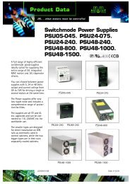
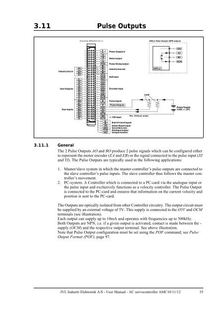
3.11 Pulse Outputs<br />
(Connector DIN41612 ver. C)<br />
AMCxx Pulse Outputs (NPN outputs)<br />
Industry bus in<br />
<strong>User</strong> Outputs<br />
<strong>User</strong> Inputs<br />
IA1<br />
IA2<br />
IA3<br />
IA4<br />
O+<br />
O8<br />
O7<br />
O6<br />
O5<br />
O4<br />
O3<br />
O2<br />
O1<br />
O-<br />
IN8<br />
IN7<br />
IN6<br />
IN5<br />
IN4<br />
IN3<br />
IN2<br />
IN1<br />
IN-<br />
1C<br />
2C<br />
3C<br />
4C<br />
5C<br />
6C<br />
7C<br />
8C<br />
9C<br />
10C<br />
11C<br />
12C<br />
13C<br />
14C<br />
15C<br />
16C<br />
17C<br />
18C<br />
19C<br />
20C<br />
21C<br />
22C<br />
23C<br />
24C<br />
25C<br />
26C<br />
27C<br />
28C<br />
29C<br />
30C<br />
31C<br />
32C<br />
TT0014GB<br />
1A P-<br />
2A P+<br />
3A FA<br />
4A FB<br />
5A FC<br />
6A FD<br />
7A PDO<br />
8A IB1<br />
9A IB2<br />
10A IB3<br />
11A IB4<br />
12A HLA<br />
13A HLB<br />
14A HLC<br />
15A 5VO<br />
16A EZ1<br />
17A EZ2<br />
18A EA1<br />
19A EA2<br />
20A EB1<br />
21A EB2<br />
22A ECM<br />
23A XCM<br />
24A XI<br />
25A YCM<br />
26A YI<br />
27A O5V<br />
28A AO<br />
29A BO<br />
30A OCM<br />
31A AIN<br />
32A ACM<br />
26B<br />
27B<br />
28B<br />
30B<br />
31B<br />
32B<br />
NL<br />
PL<br />
HM<br />
AX2<br />
TCM<br />
TAC<br />
Power Supply in<br />
Motoroutput<br />
PowerDumpoutput<br />
Industry bus out<br />
Hallinput<br />
Encoder Input<br />
Pulse Inputs<br />
Pulse Outputs<br />
+/-10V Input<br />
End-of-travelinputs<br />
Home (Reset)Input<br />
Secondary axis<br />
Analogueoutput<br />
(torque monitor)<br />
Load<br />
Max. 10mA per output<br />
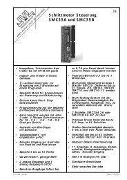
AMCxx<br />
27A<br />
28A<br />
29A<br />
30A<br />
+<br />
O5V<br />
AO<br />
BO<br />
OCM<br />
PowerSupply<br />
5 VDC +/-10%<br />
3.11.1 General<br />
The 2 Pulse Outputs AO and BO produce 2 pulse signals which can be configured either<br />
to represent the motor encoder (EA and EB) or the signal connected to the pulse input (XI<br />
and YI). The Pulse Outputs are typically used in the following applications:<br />
1. Master/slave system in which the master-controller’s pulse outputs are connected to<br />
the slave controller’s pulse inputs. The slave controller thus follows the master controller’s<br />
movement.<br />
2. PC-system. A Controller which is connected to a PC-card via the analogue input or<br />
the pulse input and exclusively functions as a velocity controller. The Pulse Output<br />
is connected to the PC-card and ensures that information on the current velocity and<br />
position is sent to the PC-card.<br />
The Outputs are optically isolated from other Controller circuitry. The output circuit must<br />
be supplied by an external voltage of 5V. This supply is connected to the O5V and OCM<br />
terminals (see illustration).<br />
Each output can supply up to 10mA and operates with frequencies up to 500kHz.<br />
Both Outputs are NPN, i.e. if a given output is activated, contact is made between the -<br />
supply (OCM) and the respective output terminal. See above illustration.<br />
Note that Pulse Output configuration must be set using the POF command; see Pulse<br />
Output Format (POF), page 97.<br />
<strong>JVL</strong> <strong>Industri</strong> <strong>Elektronik</strong> A/S - <strong>User</strong> <strong>Manual</strong> - AC servocontroller AMC10/11/12 35