User Manual - JVL Industri Elektronik A/S
User Manual - JVL Industri Elektronik A/S
User Manual - JVL Industri Elektronik A/S

You also want an ePaper? Increase the reach of your titles
YUMPU automatically turns print PDFs into web optimized ePapers that Google loves.
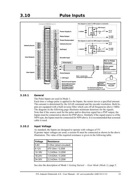
3.10 Pulse Inputs<br />
(Connector DIN41612 ver. C)<br />
This diagram is used if a PNP output is connected<br />
PNP Output<br />
Industry bus in<br />
<strong>User</strong> Outputs<br />
<strong>User</strong> Inputs<br />
IA1<br />
IA2<br />
IA3<br />
IA4<br />
O+<br />
O8<br />
O7<br />
O6<br />
O5<br />
O4<br />
O3<br />
O2<br />
O1<br />
O-<br />
IN8<br />
IN7<br />
IN6<br />
IN5<br />
IN4<br />
IN3<br />
IN2<br />
IN1<br />
IN-<br />
1C<br />
2C<br />
3C<br />
4C<br />
5C<br />
6C<br />
7C<br />
8C<br />
9C<br />
10C<br />
11C<br />
12C<br />
13C<br />
14C<br />
15C<br />
16C<br />
17C<br />
18C<br />
19C<br />
20C<br />
21C<br />
22C<br />
23C<br />
24C<br />
25C<br />
26C<br />
27C<br />
28C<br />
29C<br />
30C<br />
31C<br />
32C<br />
TT0032GB<br />
1A P-<br />
2A P+<br />
3A FA<br />
4A FB<br />
5A FC<br />
6A FD<br />
7A PDO<br />
8A IB1<br />
9A IB2<br />
10A IB3<br />
11A IB4<br />
12A HLA<br />
13A HLB<br />
14A HLC<br />
15A 5VO<br />
16A EZ1<br />
17A EZ2<br />
18A EA1<br />
19A EA2<br />
20A EB1<br />
21A EB2<br />
22A ECM<br />
23A XCM<br />
24A XI<br />
25A YCM<br />
26A YI<br />
27A O5V<br />
28A AO<br />
29A BO<br />
30A OCM<br />
31A AIN<br />
32A ACM<br />
26B NL<br />
27B PL<br />
28B HM<br />
30B AX2<br />
31B TCM<br />
32B TAC<br />
Power Supply in<br />
Motor Output<br />
Power Dump output<br />
Industry bus out<br />
Hall Input<br />
Encoder Input<br />
Pulse Inputs<br />
Pulse Outputs<br />
+/- 10V Input<br />
End-of-travel inputs<br />
Home (Reset) input<br />
Secondary axis<br />
Analogue output<br />
(torque monitor)<br />
5-30VDC<br />
+<br />
+<br />
Pulse<br />
source<br />
This diagram is used if an NPN output is connected<br />
Screen<br />
Pulse<br />
source<br />
Note !: screen only<br />
connected to signal source.<br />
R<br />
R<br />
NPN Output<br />
Channel A<br />
Ground<br />
Channel B<br />
For electronic gearing an<br />
incremental encoder is used<br />
To XI<br />
or YI<br />
To XCM<br />
or YCM<br />
To XI<br />
or YI<br />
To XCM<br />
or YCM<br />
PLC or Pulse<br />
Generator<br />
Pulse output<br />
Ground<br />
Direction output<br />
PNP outputs<br />
3.10.1 General<br />
The Pulse Inputs are used in Mode 1.<br />
Each time a voltage pulse is applied to the Inputs, the motor moves a specified amount.<br />
This amount is determined by the GEAR command and the encoder resolution. Both Inputs<br />
are equipped with a built-in noise filter which cuts off all frequencies above 1MHz.<br />
The diagram on the following page illustrates minimum durations for the signals.<br />
Note that if the source used for the pulse and/or direction signal has a PNP output, the<br />
Inputs must be connected as shown for PNP above. Similarly if the signal source is of the<br />
NPN type, the Inputs must be connected for NPN above. It is recommended that screened<br />
cable is used.<br />
3.10.2 Input Voltage<br />
As standard, the Inputs are designed to operate with voltages of 5V.<br />
If greater input voltages are used, a resistor R must be connected as shown in the above<br />
illustration. The value of the required resistance is given in the following table.<br />
Voltage<br />
Resistance<br />
5-8V 0 Ohm (short-circuited)<br />
8-12V 470 Ohm / 0.25W<br />
12-18V 1.2 kOhm / 0.25W<br />
18-24V 1.8 kOhm / 0.25W<br />
24-30V 2.2 kOhm / 0.25W<br />
See also the description of Mode 1 Getting Started — Gear Mode (Mode 1), page 5.<br />
<strong>JVL</strong> <strong>Industri</strong> <strong>Elektronik</strong> A/S - <strong>User</strong> <strong>Manual</strong> - AC servocontroller AMC10/11/12 33