User Manual - JVL Industri Elektronik A/S
User Manual - JVL Industri Elektronik A/S
User Manual - JVL Industri Elektronik A/S

Create successful ePaper yourself
Turn your PDF publications into a flip-book with our unique Google optimized e-Paper software.
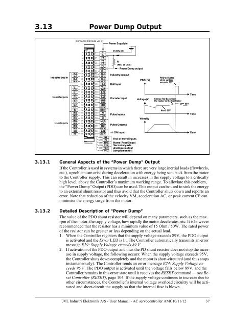
3.13 Power Dump Output<br />
(Connector DIN41612 ver. C)<br />
PowerSupplyin<br />
+<br />
Industrybusin<br />
<strong>User</strong>Outputs<br />
<strong>User</strong> Inputs<br />
IA1<br />
IA2<br />
IA3<br />
IA4<br />
O+<br />
O8<br />
O7<br />
O6<br />
O5<br />
O4<br />
O3<br />
O2<br />
O1<br />
O-<br />
IN8<br />
IN7<br />
IN6<br />
IN5<br />
IN4<br />
IN3<br />
IN2<br />
IN1<br />
IN-<br />
1C<br />
2C<br />
3C<br />
4C<br />
5C<br />
6C<br />
7C<br />
8C<br />
9C<br />
10C<br />
11C<br />
12C<br />
13C<br />
14C<br />
15C<br />
16C<br />
17C<br />
18C<br />
19C<br />
20C<br />
21C<br />
22C<br />
23C<br />
24C<br />
25C<br />
26C<br />
27C<br />
28C<br />
29C<br />
30C<br />
31C<br />
32C<br />
TT0035GB<br />
1A P-<br />
2A P+<br />
3A FA<br />
4A FB<br />
5A FC<br />
6A FD<br />
7A PDO<br />
8A IB1<br />
9A IB2<br />
10A IB3<br />
11A IB4<br />
12A HLA<br />
13A HLB<br />
14A HLC<br />
15A 5VO<br />
16A EZ1<br />
17A EZ2<br />
18A EA1<br />
19A EA2<br />
20A EB1<br />
21A EB2<br />
22A ECM<br />
23A XCM<br />
24A XI<br />
25A YCM<br />
26A YI<br />
27A O5V<br />
28A AO<br />
29A BO<br />
30A OCM<br />
31A AIN<br />
32A ACM<br />
26B NL<br />
27B PL<br />
28B HM<br />
30B AX2<br />
31B TCM<br />
32B TAC<br />
15-80V DC<br />
HallInput<br />
R<br />
(Min. 15 Ohm)<br />
Encoder Input<br />
Pulse Inputs<br />
Pulse Outputs<br />
+/-10V Input<br />
PowerDumpoutput<br />
Industrybus out<br />
End-of-travelinputs<br />
Home (Reset)input<br />
Secondaryaxis<br />
Analogueoutput<br />
(torque monitor)<br />
PDO (V)<br />
Voltage (V)<br />
Velocity<br />
PDO activated<br />
when voltage<br />
exceeds 89V<br />
Energy fed back from<br />
the motor to the Controller<br />
Nom. 80V<br />
Time<br />
89V<br />
Time<br />
Time<br />
3.13.1 General Aspects of the “Power Dump” Output<br />
If the Controller is used in systems in which there are very large inertial loads (flywheels,<br />
etc.), a problem can arise during deceleration with energy being sent back from the motor<br />
to the Controller supply. This can result in increases in the supply voltage to a critically<br />
high level, above the Controller’s maximum working range. To alleviate this problem,<br />
the “Power Dump” Output (PDO) can be used. This output can be used to sink the energy<br />
to an external shunt resistor and thus avoid that the Controller shuts down and reports an<br />
error. Note that reduction of the velocity VM, acceleration AC, or peak current CP can<br />
minimise the energy surge from the motor.<br />
3.13.2 Detailed Description of “Power Dump”<br />
The value of the PDO shunt resistor will depend on many parameters, such as the max.<br />
rpm of the motor, the supply voltage, how rapidly the motor decelerates, etc. It is however<br />
recommended that the resistor has a minimum value of 15 Ohm / 50W. The rated power<br />
of the resistor can be greater or less depending on the actual load.<br />
1. When the Controller registers that the supply voltage exceeds 89V, the PDO output<br />
is activated and the Error LED is lit. The Controller automatically transmits an error<br />
message E29: Supply Voltage exceeds 89 V.<br />
2. If activation of the PDO output and thus the PD shunt resistor does not stop the increase<br />
in supply voltage, the following occurs: When the supply voltage exceeds 95V,<br />
the Controller shuts down completely and the motor is short-circuited (and thus stops<br />
instantaneously). The Controller sends an error message E24: Supply Voltage exceeds<br />
95 V. The PDO output is activated until the voltage falls below 89V, and the<br />
Controller remains in this error state until it receives the RESET command — see Reset<br />
Controller (RESET), page 104. If the supply voltage continues to increase due to<br />
other circumstances, the Controller’s internal voltage overload circuitry will be activated<br />
and short-circuit the supply so that the internal fuse is blown.<br />
<strong>JVL</strong> <strong>Industri</strong> <strong>Elektronik</strong> A/S - <strong>User</strong> <strong>Manual</strong> - AC servocontroller AMC10/11/12 37