User Manual - JVL Industri Elektronik A/S
User Manual - JVL Industri Elektronik A/S
User Manual - JVL Industri Elektronik A/S

Create successful ePaper yourself
Turn your PDF publications into a flip-book with our unique Google optimized e-Paper software.
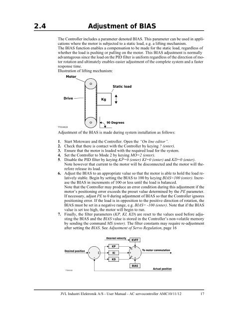
2.4 Adjustment of BIAS<br />
The Controller includes a parameter denoted BIAS. This parameter can be used in applications<br />
where the motor is subjected to a static load, e.g. a lifting mechanism.<br />
The BIAS function enables a compensation to be made for the static load, regardless of<br />
whether the load is pushing or pulling on the motor. This BIAS adjustment is normally<br />
advantageous since the load on the PID filter is uniform regardless of the direction of motor<br />
rotation and ultimately enables easier adjustment of the complete system and a faster<br />
response time.<br />
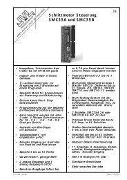
Illustration of lifting mechanism:<br />
Motor<br />
Static load<br />
Drive<br />
Kg<br />
TT0040GB<br />
90 Degrees<br />
Adjustment of the BIAS is made during system installation as follows:<br />
1. Start Motoware and the Controller. Open the “On line editor”.<br />
2. Check that there is contact with the Controller by keying ? (enter).<br />
3. Ensure that the motor is loaded with the required load for the system.<br />
4. Set the Controller to Mode 2 by keying MO=2 (enter).<br />
5. Disable the PID filter by keying KP=0 (enter) KI=0 (enter) and KD=0 (enter).<br />
Note however that current to the motor will be disconnected and the motor will therefore<br />
release its load.<br />
6. Adjust the BIAS to an appropriate value so that the motor is able to hold the load relatively<br />
stable. Begin by setting the BIAS to 100 by keying BIAS=100 (enter). Increase<br />
the BIAS in increments of 100 or less until the load is balanced.<br />
Note that the Controller may produce an error condition during this adjustment if the<br />
motor’s positioning error exceeds the preset value determined by the PE parameter.<br />
If necessary, adjust PE to 0 during adjustment of BIAS so that the Controller ignores<br />
positioning error. If the load is in opposition to the positive direction of rotation, the<br />
BIAS must be set in a negative range, e.g. BIAS= -100 (enter). Note that if the BIAS<br />
value is set too high, the motor will begin to run.<br />
7. Finally, the filter parameters (KP, KI, KD) are reset to the values used before adjusting<br />
the BIAS and the BIAS value is stored in the Controller’s non-volatile memory<br />
by sending the command MS (enter). The filter constants may require re-adjustment<br />
after setting the BIAS. See Adjustment of Servo Regulation, page 16<br />
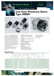
Desired velocity<br />
KVFF<br />
Desired position<br />
+<br />
KP<br />
KI<br />
+ +<br />
+<br />
+ +<br />
To motor commutation<br />
KD<br />
TT0041GB<br />
BIAS<br />
Actual position<br />
<strong>JVL</strong> <strong>Industri</strong> <strong>Elektronik</strong> A/S - <strong>User</strong> <strong>Manual</strong> - AC servocontroller AMC10/11/12 17