User Manual - JVL Industri Elektronik A/S
User Manual - JVL Industri Elektronik A/S
User Manual - JVL Industri Elektronik A/S

You also want an ePaper? Increase the reach of your titles
YUMPU automatically turns print PDFs into web optimized ePapers that Google loves.
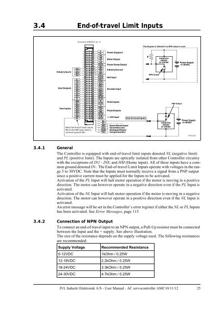
3.4 End-of-travel Limit Inputs<br />
(Connector DIN41612 ver. C)<br />
This diagram is followed if an NPN output is used<br />
Industrybus in<br />
<strong>User</strong>Outputs<br />
<strong>User</strong> Inputs<br />
IA1<br />
IA2<br />
IA3<br />
IA4<br />
O+<br />
O8<br />
O7<br />
O6<br />
O5<br />
O4<br />
O3<br />
O2<br />
O1<br />
O-<br />
IN8<br />
IN7<br />
IN6<br />
IN5<br />
IN4<br />
IN3<br />
IN2<br />
IN1<br />
IN-<br />
1C<br />
2C<br />
3C<br />
4C<br />
5C<br />
6C<br />
7C<br />
8C<br />
9C<br />
10C<br />
11C<br />
12C<br />
13C<br />
14C<br />
15C<br />
16C<br />
17C<br />
18C<br />
19C<br />
20C<br />
21C<br />
22C<br />
23C<br />
24C<br />
25C<br />
26C<br />
27C<br />
28C<br />
29C<br />
30C<br />
31C<br />
32C<br />
Note that End-of-travel inputs,<br />
IN1-8 and HM input share a<br />
common ground (IN-)<br />
1A P-<br />
2A P+<br />
3A FA<br />
4A FB<br />
5A FC<br />
6A FD<br />
7A PDO<br />
8A IB1<br />
9A IB2<br />
10A IB3<br />
11A IB4<br />
12A HLA<br />
13A HLB<br />
14A HLC<br />
15A 5VO<br />
16A EZ1<br />
17A EZ2<br />
18A EA1<br />
19A EA2<br />
20A EB1<br />
21A EB2<br />
22A ECM<br />
23A XCM<br />
24A XI<br />
25A YCM<br />
26A YI<br />
27A O5V<br />
28A AO<br />
29A BO<br />
30A OCM<br />
31A AIN<br />
32A ACM<br />
26B<br />
27B<br />
28B<br />
30B<br />
31B<br />
32B<br />
NL<br />
PL<br />
HM<br />
AX2<br />
TCM<br />
TAC<br />
Power Supplyin<br />
Motor Output<br />
Power Dump Output<br />
Industrybus out<br />
Hall Input<br />
Encoder Input<br />
PulseInputs<br />
PulseOutputs<br />
+/-10V Input<br />
Home(Reset)Input<br />
Secondaryaxis<br />
AnalogueOutput<br />
(torquemonitor)<br />
End-of-travel Inputs<br />
R<br />
NPN Output<br />
Inductive<br />
sensor<br />
or similar<br />
Inductive<br />
sensor<br />
or similar<br />
+<br />
PNP Output<br />
+<br />
Power Supply<br />
+5-30VDC<br />
Power Supply<br />
+5-30VDC<br />
TT0012GB<br />
3.4.1 General<br />
The Controller is equipped with end-of-travel limit inputs denoted NL (negative limit)<br />
and PL (positive limit). The Inputs are optically isolated from other Controller circuitry<br />
with the exceptions of IN1 - IN8, and HM (Home input). All of these inputs have a common<br />
ground denoted IN-. The End-of-travel Limit Inputs operate with voltages in the range<br />
5 to 30VDC. Note that the Inputs must normally receive a signal from a PNP output<br />
since a positive current must be applied for the Inputs to be activated.<br />
Activation of the PL Input will halt motor operation if the motor is moving in a positive<br />
direction. The motor can however operate in a negative direction even if the PL Input is<br />
activated.<br />
Activation of the NL Input will halt motor operation if the motor is moving in a negative<br />
direction. The motor can however operate in a positive direction even if the NL Input is<br />
activated.<br />
An error message will be set in the Controller’s error register if either the NL or PL Inputs<br />
has been activated. See Error Messages, page 115<br />
3.4.2 Connection of NPN Output<br />
To connect an end-of-travel input to an NPN output, a Pull-Up resistor must be connected<br />
between the Input and the + supply. See above illustration.<br />
The size of the resistance depends on the supply voltage used. The following resistances<br />
are recommended:<br />
Supply Voltage<br />
Recommended Resistance<br />
5-12VDC 1kOhm / 0.25W<br />
12-18VDC 2.2kOhm / 0.25W<br />
18-24VDC 3.3kOhm / 0.25W<br />
24-30VDC 4.7kOhm / 0.25W<br />
<strong>JVL</strong> <strong>Industri</strong> <strong>Elektronik</strong> A/S - <strong>User</strong> <strong>Manual</strong> - AC servocontroller AMC10/11/12 25