User Manual - JVL Industri Elektronik A/S
User Manual - JVL Industri Elektronik A/S
User Manual - JVL Industri Elektronik A/S

Create successful ePaper yourself
Turn your PDF publications into a flip-book with our unique Google optimized e-Paper software.
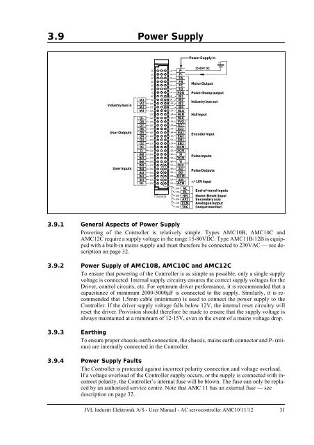
3.9 Power Supply<br />
Industrybus in<br />
<strong>User</strong> Outputs<br />
<strong>User</strong> Inputs<br />
IA1<br />
IA2<br />
IA3<br />
IA4<br />
O+<br />
O8<br />
O7<br />
O6<br />
O5<br />
O4<br />
O3<br />
O2<br />
O1<br />
O-<br />
IN8<br />
IN7<br />
IN6<br />
IN5<br />
IN4<br />
IN3<br />
IN2<br />
IN1<br />
IN-<br />
1C<br />
2C<br />
3C<br />
4C<br />
5C<br />
6C<br />
7C<br />
8C<br />
9C<br />
10C<br />
11C<br />
12C<br />
13C<br />
14C<br />
15C<br />
16C<br />
17C<br />
18C<br />
19C<br />
20C<br />
21C<br />
22C<br />
23C<br />
24C<br />
25C<br />
26C<br />
27C<br />
28C<br />
29C<br />
30C<br />
31C<br />
32C<br />
TT0030GB<br />
1A P-<br />
2A P+<br />
3A FA<br />
4A FB<br />
5A FC<br />
6A FD<br />
7A PDO<br />
8A IB1<br />
9A IB2<br />
10A IB3<br />
11A IB4<br />
12A HLA<br />
13A HLB<br />
14A HLC<br />
15A 5VO<br />
16A EZ1<br />
17A EZ2<br />
18A EA1<br />
19A EA2<br />
20A EB1<br />
21A EB2<br />
22A ECM<br />
23A XCM<br />
24A XI<br />
25A YCM<br />
26A YI<br />
27A O5V<br />
28A AO<br />
29A BO<br />
30A OCM<br />
31A AIN<br />
32A ACM<br />
26B NL<br />
27B PL<br />
28B HM<br />
30B AX2<br />
31B TCM<br />
32B TAC<br />
Power Supply in<br />
15-80V DC<br />
Motor Output<br />
Power Dump output<br />
Industry bus out<br />
Hall Input<br />
Encoder Input<br />
Pulse Inputs<br />
PulseOutputs<br />
+/- 10V Input<br />
+<br />
End-of-travel inputs<br />
Home (Reset)input<br />
Secondaryaxis<br />
Analogueoutput<br />
(torque monitor)<br />
3.9.1 General Aspects of Power Supply<br />
Powering of the Controller is relatively simple. Types AMC10B, AMC10C and<br />
AMC12C require a supply voltage in the range 15-80VDC. Type AMC11B/12B is equipped<br />
with a built-in mains supply and must therefore be connected to 230VAC — see description<br />
on page 32.<br />
3.9.2 Power Supply of AMC10B, AMC10C and AMC12C<br />
To ensure that powering of the Controller is as simple as possible, only a single supply<br />
voltage is connected. Internal supply circuitry ensures the correct supply voltages for the<br />
Driver, control circuits, etc. For optimum driver performance, it is recommended that a<br />
capacitance of minimum 2000-5000µF is connected to the supply. Similarly, it is recommended<br />
that 1.5mm cable (minimum) is used to connect the power supply to the<br />
Controller. If the driver supply voltage falls below 12V, the internal reset circuitry will<br />
reset the driver. Provision should therefore be made to ensure that the supply voltage is<br />
always maintained at a minimum of 12-15V, even in the event of a mains voltage drop.<br />
3.9.3 Earthing<br />
To ensure proper chassis-earth connection, the chassis, mains earth connector and P- (minus)<br />
are internally connected in the Controller.<br />
3.9.4 Power Supply Faults<br />
The Controller is protected against incorrect polarity connection and voltage overload.<br />
If a voltage overload of the Controller supply occurs, or the supply is connected with incorrect<br />
polarity, the Controller’s internal fuse will be blown. The fuse can only be replaced<br />
by an authorised service centre. Note that AMC 11 has an external fuse — see<br />
description on page 32.<br />
<strong>JVL</strong> <strong>Industri</strong> <strong>Elektronik</strong> A/S - <strong>User</strong> <strong>Manual</strong> - AC servocontroller AMC10/11/12 31