fiber products
fiber products
fiber products

You also want an ePaper? Increase the reach of your titles
YUMPU automatically turns print PDFs into web optimized ePapers that Google loves.
Index<br />
Work Area<br />
Installation<br />
Practices<br />
Shielded<br />
Products<br />
Modular<br />
Patching<br />
Racks and<br />
Cable<br />
Management<br />
S110<br />
Products<br />
Fiber<br />
Products<br />
WORK AREA<br />
Primary location where the building occupants interact with dedicated telecommunications equipment.<br />
Patch Cords,<br />
Plugs and<br />
Cable<br />
S210<br />
Products<br />
Design Considerations:<br />
• At least one telecommunication outlet box location shall be planned for each work area.<br />
• This location should be coordinated with the furniture plan. A power outlet should be nearby.<br />
• Control center, attendant, and reception areas shall have direct and independent pathways to the serving telecommunications room.<br />
• Furniture System Design:<br />
– Cable access via walls, columns, ceilings, or floors. Fittings that transition between building and furniture pathways require special planning.<br />
– Furniture pathway fill capacity is effectively reduced by furniture corners, and connectors mounted within the furniture pathway systems.<br />
– Furniture pathways bend radius shall not force the installed cable to a bend radius of less than 25mm (1 in.).<br />
– Furniture spaces designed to house slack storage, consolidation points, or multi-user telecommunications outlet assemblies shall provide space for<br />
strain relieving, terminating, and storing slack for the horizontal cables.<br />
– Slack storage and furniture pathway fill, shall not affect the bend radius and termination of the cable to the connector.<br />
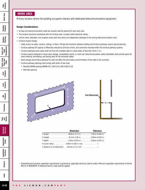
– Furniture pathway openings shall comply with either of two sizes:<br />
• Standard NEMA opening (NEMA OS 1 [Ref D.14], WD-6 [Ref D.15])<br />
• Alternate opening:<br />
L<br />
S66<br />
Products<br />
H<br />
First Obstruction<br />
Protection<br />
T<br />
C<br />
Tools<br />
and<br />
Testers<br />
R<br />
Standards<br />
Overview<br />
Application<br />
Guide<br />
Dimension<br />
Tolerance<br />
L (length) . . . . . . . . . . . . . . . . . . . . . 68.8mm (2.71 in.) . . . . . . . . . . 1.02mm (0.040 in.)<br />
H (height) . . . . . . . . . . . . . . . . . . . . 35.1mm (1.38 in.) . . . . . . . . . . 0.90mm (0.035 in.)<br />
T (depth) . . . . . . . . . . . . . . . . . . . . . 1.40mm (0.055 in.) . . . . . . . . . . 0.64mm (0.025 in.)<br />
R (corner radius) . . . . . . . . . . . . 4.06mm (0.160 in.) max . . . . . . . . . . . . . . —<br />
C (distance to 1st obstruction) . . . 30.5mm (1.2 in.) min . . . . . . . . . . . . . . . —<br />
Glossary<br />
– Power/telecommunication separation requirements is governed by applicable electrical code for safety. Minimum separation requirements of Article<br />
800-52 of ANSI/NFPA 70 (National Electric Code) shall be applied.<br />
12•28<br />
T H E S I E M O N . C O M P A N Y