fiber products
fiber products
fiber products

Create successful ePaper yourself
Turn your PDF publications into a flip-book with our unique Google optimized e-Paper software.
Index<br />
Work Area<br />
Standards<br />
Overview<br />
Racks and<br />
Cable<br />
Management<br />
S66<br />
Products<br />
Patch Cords,<br />
Plugs and<br />
Cable<br />
S110<br />
Products<br />
S210<br />
Products<br />
Modular<br />
Patching<br />
Shielded<br />
Products<br />
Fiber<br />
Products<br />
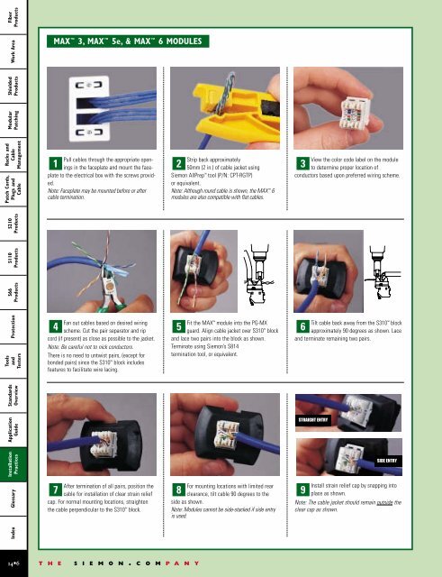
MAX 3, MAX 5e, & MAX 6 MODULES<br />
1 2 3<br />
Pull cables through the appropriate openings<br />
in the faceplate and mount the faceplate<br />
to the electrical box with the screws provided.<br />
Note: Faceplate may be mounted before or after<br />
cable termination.<br />
Strip back approximately<br />
50mm (2 in.) of cable jacket using<br />
Siemon AllPrep tool (P/N: CPT-RGTP)<br />
or equivalent.<br />
Note: Although round cable is shown, the MAX 6<br />
modules are also compatible with flat cables.<br />
View the color code label on the module<br />
to determine proper location of<br />
conductors based upon preferred wiring scheme.<br />
Protection<br />
Tools<br />
and<br />
Testers<br />
4 5 6<br />
Fan out cables based on desired wiring<br />
scheme. Cut the pair separator and rip<br />
cord (if present) as close as possible to the jacket.<br />
Note: Be careful not to nick conductors.<br />
There is no need to untwist pairs, (except for<br />
bonded pairs) since the S310 block includes<br />
features to facilitate wire lacing.<br />
Fit the MAX module into the PG-MX<br />
guard. Align cable jacket over S310 block<br />
and lace two pairs into the block as shown.<br />
Terminate using Siemon’s S814<br />
termination tool, or equivalent.<br />
Tilt cable back away from the S310 block<br />
approximately 90 degrees as shown. Lace<br />
and terminate remaining two pairs.<br />
Application<br />
Guide<br />
STRAIGHT ENTRY<br />
Installation<br />
Practices<br />
Glossary<br />
7 8 9<br />
After termination of all pairs, position the<br />
cable for installation of clear strain relief<br />
cap. For normal mounting locations, straighten<br />
the cable perpendicular to the S310 block.<br />
For mounting locations with limited rear<br />
clearance, tilt cable 90 degrees to the<br />
side as shown.<br />
Note: Modules cannot be side-stacked if side entry<br />
is used.<br />
SIDE ENTRY<br />
Install strain relief cap by snapping into<br />
place as shown.<br />
Note: The cable jacket should remain outside the<br />
clear cap as shown.<br />
14•6<br />
T H E S I E M O N . C O M P A N Y