
Create successful ePaper yourself
Turn your PDF publications into a flip-book with our unique Google optimized e-Paper software.
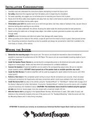
W IRING THE SYSTEM<br />
NOTICE: If you do not feel comfortable with wiring your new<br />
source unit, please see your local Authorized Rockford Fosgate<br />
Dealer for assistance.<br />
• For safety, disconnect the negative lead from the battery prior to<br />
beginning the installation.<br />
1. Install the 22-Pin/Power Harness by connecting the corresponding<br />
wires to the electrical and audio system. Solder and heat<br />
shrink all connections for a reliable installation. For each connection,<br />
cut a 1" piece of heat shrink tubing and slide over one of the<br />
wires. Strip each wire 3/8" then twist together and solder. Slide<br />
the tubing over the connection and shrink the tubing with a hot<br />
air gun until no bare wire is exposed.<br />
The BLACK Wire (Chassis Ground) supplies –power ground for<br />
the source unit. Prepare the chassis ground by scraping any paint<br />
from the metal surface and thoroughly clean the area of all dirt<br />
and grease. Strip the end of the wire and attach a ring connector.<br />
Fasten the wire to the chassis using a non-anodized screw and<br />
star washer.<br />
The RED Wire (Ignition) allows the source unit to turn on only<br />
when the ignition key is in the “accessory” or “run” position.<br />
Connect the RED wire to a switched 12 volt positive source. The<br />
switched signal is usually taken from the ACC (accessory) position<br />
of the ignition. If the vehicle does not have an ACC position,<br />
connect the wire to the switched ON position of the ignition. The<br />
current consumption through this wire is negligible.<br />
The YELLOW Wire (Battery) is the main power wire and retains<br />
memory for user-programmed functions. Connect the Yellow<br />
wire to a constant 12 volt positive source. The source should<br />
always have +12V, even when the ignition is off and the car is not<br />
running.<br />
The LT. BLUE Wire (Turn-On “A”) is the primary accessory turnon<br />
wire which provides immediate turn-on and .5 sec delayed<br />
turn-off. Connect the Lt. Blue wire to the “Remote Turn-On”<br />
leads of any external equalizers or crossovers which cause on/<br />
off transients (pops or thumps) in the system. The maximum<br />
current available from this lead is 2 Amps.<br />
– 15 –