

guide to thin section microscopy - Mineralogical Society of America
guide to thin section microscopy - Mineralogical Society of America
guide to thin section microscopy - Mineralogical Society of America

Create successful ePaper yourself
Turn your PDF publications into a flip-book with our unique Google optimized e-Paper software.
Guide <strong>to</strong> Thin Section Microscopy<br />
Conoscopy<br />
Determining the optic sign <strong>of</strong> uniaxial minerals<br />
For the determination <strong>of</strong> optic sign, crystal <strong>section</strong>s are required that are either isotropic or<br />
show very low interference colours in orthoscopic view. The conoscopic interference figure<br />
will then show a more or less centred, dark isogyre cross.<br />
If the first-order red plate is inserted, the cross will appear in 1 st -order red, while the four<br />
quadrants display two different sequences <strong>of</strong> interference colours, depending on the vibration<br />
direction <strong>of</strong> the E- and O-waves. Two cases have <strong>to</strong> be distinguished:<br />
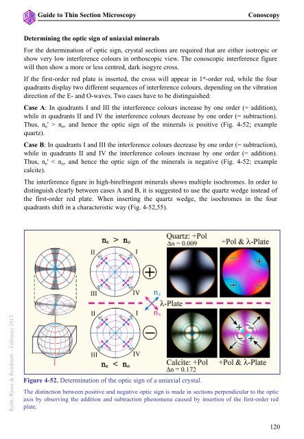
Case A: In quadrants I and III the interference colours increase by one order (= addition),<br />
while in quadrants II and IV the interference colours decrease by one order (= subtraction).<br />
Thus, n e ' > n o , and hence the optic sign <strong>of</strong> the minerals is positive (Fig. 4-52; example<br />
quartz).<br />
Case B: In quadrants I and III the interference colours decrease by one order (= subtraction),<br />
while in quadrants II and IV the interference colours increase by one order (= addition).<br />
Thus, n e ' < n o , and hence the optic sign <strong>of</strong> the minerals is negative (Fig. 4-52; example<br />
calcite).<br />
The interference figure in high-birefringent minerals shows multiple isochromes. In order <strong>to</strong><br />
distinguish clearly between cases A and B, it is suggested <strong>to</strong> use the quartz wedge instead <strong>of</strong><br />
the first-order red plate. When inserting the quartz wedge, the isochromes in the four<br />
quadrants shift in a characteristic way (Fig. 4-52,55).<br />
Raith, Raase & Reinhardt – February 2012<br />
Figure 4-52. Determination <strong>of</strong> the optic sign <strong>of</strong> a uniaxial crystal.<br />
The distinction between positive and negative optic sign is made in <strong>section</strong>s perpendicular <strong>to</strong> the optic<br />
axis by observing the addition and subtraction phenomena caused by insertion <strong>of</strong> the first-order red<br />
plate.<br />
120


