3100B HFOV Operator Manual - CareFusion
3100B HFOV Operator Manual - CareFusion
3100B HFOV Operator Manual - CareFusion
Create successful ePaper yourself
Turn your PDF publications into a flip-book with our unique Google optimized e-Paper software.
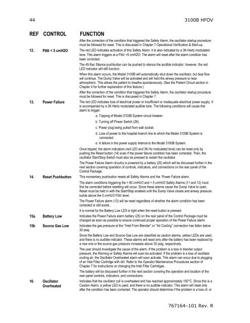
44 <strong>3100B</strong> <strong>HFOV</strong><br />
REF CONTROL<br />
FUNCTION<br />
After the correction of the condition that triggered the Safety Alarm, the oscillator startup procedure<br />
must be followed for reset. This is discussed in Chapter 7 Operational Verification & Start-up.<br />
12. Pa < 5 cmH2O The red LED indicates activation of this Safety Alarm. It is also indicated by a 3K-Hertz modulated<br />
tone. This alarm triggers at a Pa 60 cmH2O and < 5 cmH2O Safety Alarms (11 and 12) must<br />
first be corrected before resetting will occur. Since these alarms cause the Dump Valve to open,<br />
Reset must be held in with the Start/Stop enabled until the Dump Valve closes and airway pressure<br />
builds above the 5 cmH2O Pa level.<br />
The Power Failure alarm (13) will be reset regardless of whether the alarm condition has been<br />
corrected or still exists.<br />
It is normal for the Battery Low LED to light when the reset button is pressed.<br />
15a. Battery Low Indicates the Power Failure alarm battery (25) on the rear panel of the Control Package must be<br />
changed as soon as possible to ensure continued proper operation of the Power Failure alarm.<br />
15b Source Gas Low Indicates the gas pressure at the “Inlet From Blender” or “Air Cooling” connection has fallen below<br />
30 psig.<br />
Since the Battery Low and Source Gas Low are classified as caution alarms, yellow LEDs are used,<br />
and there is no audible indicator. These alarms will reset only after the battery has been replaced by<br />
a new one or the source gas pressure increases above 30 psig, respectively.<br />
The user should investigate the cause of the alarm. If the problem is a loss in blender output<br />
pressure, the Warning or Safety Alarms will soon be activated. If the problem is a loss of oscillator<br />
cooling air, the Oscillator Overheated alarm will soon activate. This alarm can occur due to plugging<br />
of an Inlet Filter Cartridge with dirt. Refer to the <strong>Operator</strong> Maintenance Procedures section of<br />
Chapter 7 for instructions on changing the Inlet Filter Cartridges.<br />
The battery will be discussed further in the next section covering the operation and location of the<br />
rear panel controls, indicators, and connections.<br />
16. Oscillator<br />
Overheated<br />
Indicates that the oscillator coil is overheated and has reached approximately 150°C. Since this is a<br />
Caution Alarm, a yellow LED is used, and there is no audible indicator. This alarm will reset only<br />
after the condition has been corrected. The operator should determine if the problem is a loss of, or<br />
767164–101 Rev. R


