3100B HFOV Operator Manual - CareFusion
3100B HFOV Operator Manual - CareFusion
3100B HFOV Operator Manual - CareFusion

You also want an ePaper? Increase the reach of your titles
YUMPU automatically turns print PDFs into web optimized ePapers that Google loves.
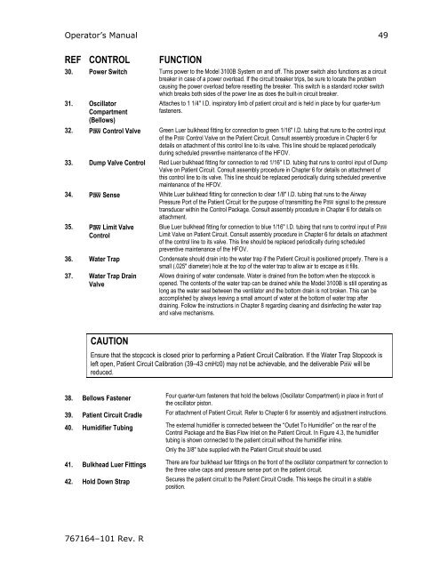
<strong>Operator</strong>’s <strong>Manual</strong> 49<br />
REF CONTROL<br />
FUNCTION<br />
30. Power Switch Turns power to the Model <strong>3100B</strong> System on and off. This power switch also functions as a circuit<br />
breaker in case of a power overload. If the circuit breaker trips, be sure to locate the problem<br />
causing the power overload before resetting the breaker. This switch is a standard rocker switch<br />
which breaks both sides of the power line as does the built-in circuit breaker.<br />
31. Oscillator<br />
Compartment<br />
(Bellows)<br />
Attaches to 1 1/4" I.D. inspiratory limb of patient circuit and is held in place by four quarter-turn<br />
fasteners.<br />
32. Pa Control Valve Green Luer bulkhead fitting for connection to green 1/16" I.D. tubing that runs to the control input<br />
of the Pa Control Valve on the Patient Circuit. Consult assembly procedure in Chapter 6 for<br />
details on attachment of this control line to its valve. This line should be replaced periodically<br />
during scheduled preventive maintenance of the <strong>HFOV</strong>.<br />
33. Dump Valve Control Red Luer bulkhead fitting for connection to red 1/16" I.D. tubing that runs to control input of Dump<br />
Valve on Patient Circuit. Consult assembly procedure in Chapter 6 for details on attachment of<br />
this control line to its valve. This line should be replaced periodically during scheduled preventive<br />
maintenance of the <strong>HFOV</strong>.<br />
34. Pa Sense White Luer bulkhead fitting for connection to clear 1/8" I.D. tubing that runs to the Airway<br />
Pressure Port of the Patient Circuit for the purpose of transmitting the Pa signal to the pressure<br />
transducer within the Control Package. Consult assembly procedure in Chapter 6 for details on<br />
attachment.<br />
35. Pa Limit Valve<br />
Control<br />
Blue Luer bulkhead fitting for connection to blue 1/16" I.D. tubing that runs to control input of Pa<br />
Limit Valve on Patient Circuit. Consult assembly procedure in Chapter 6 for details on attachment<br />
of the control line to its valve. This line should be replaced periodically during scheduled<br />
preventive maintenance of the <strong>HFOV</strong>.<br />
36. Water Trap Condensate should drain into the water trap if the Patient Circuit is positioned properly. There is a<br />
small (.025" diameter) hole at the top of the water trap to allow air to escape as it fills.<br />
37. Water Trap Drain<br />
Valve<br />
Allows draining of water condensate. Water is drained from the bottom when the stopcock is<br />
opened. The contents of the water trap can be drained while the Model <strong>3100B</strong> is still operating as<br />
long as the water seal between the ventilator and the bottom drain is not broken. This can be<br />
accomplished by always leaving a small amount of water at the bottom of water trap after<br />
draining. Follow the instructions in Chapter 8 regarding cleaning and disinfecting the water trap<br />
and valve mechanisms.<br />
CAUTION<br />
Ensure that the stopcock is closed prior to performing a Patient Circuit Calibration. If the Water Trap Stopcock is<br />
left open, Patient Circuit Calibration (39–43 cmH20) may not be achievable, and the deliverable Pa will be<br />
reduced.<br />
38. Bellows Fastener Four quarter-turn fasteners that hold the bellows (Oscillator Compartment) in place in front of<br />
the oscillator piston.<br />
39. Patient Circuit Cradle For attachment of Patient Circuit. Refer to Chapter 6 for assembly and adjustment instructions.<br />
40. Humidifier Tubing The external humidifier is connected between the “Outlet To Humidifier” on the rear of the<br />
Control Package and the Bias Flow Inlet on the Patient Circuit. In Figure 4.3, the humidifier<br />
tubing is shown connected to the patient circuit without the humidifier inline.<br />
Only the 3/8" tube supplied with the Patient Circuit should be used.<br />
41. Bulkhead Luer Fittings There are four bulkhead luer fittings on the front of the oscillator compartment for connection to<br />
the three valve caps and pressure sense port on the patient circuit.<br />
42. Hold Down Strap Secures the patient circuit to the Patient Circuit Cradle. This keeps the circuit in a stable<br />
position.<br />
767164–101 Rev. R