USER'S MANUAL - DATAQ Instruments
USER'S MANUAL - DATAQ Instruments
USER'S MANUAL - DATAQ Instruments

Create successful ePaper yourself
Turn your PDF publications into a flip-book with our unique Google optimized e-Paper software.
CHAPTER 2 Checks and Preparation<br />
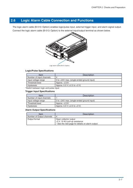
2.6 Logic Alarm Cable Connection and Functions<br />
The logic alarm cable (B-513: Option) enables logic/pulse input, external trigger input, and alarm signal output.<br />
Connect the logic alarm cable (B-513: Option) to the external input/output terminal as shown below.<br />
Logic alarm cable (B-513: Option)<br />
Logic/Pulse Specifications<br />
Item<br />
Description<br />
Number of input channels 4<br />
Input voltage range<br />
0 to +24V max. (single-ended ground input)<br />
Threshold level<br />
Approx. +2.5V<br />
Hysteresis Approx. 0.5 V (+2.5 to +3 V)<br />
*Switch between logic and pulse input.<br />
Trigger Input Specifications<br />
Item<br />
Description<br />
Number of input channels 1<br />
Input voltage range<br />
0 to +24V max. (single-ended ground input)<br />
Threshold level<br />
Approx. +2.5V<br />
Hysteresis Approx. 0.5 V (+2.5 to +3 V)<br />
Alarm Output Specifications<br />
Item<br />
Description<br />
Number of Output channels 4<br />
Output format<br />
Open collector output<br />
+5 V, 10 KΩ pull-up resistance<br />
* See the next page for details on alarm output.<br />
2−7