USER'S MANUAL - DATAQ Instruments
USER'S MANUAL - DATAQ Instruments
USER'S MANUAL - DATAQ Instruments

You also want an ePaper? Increase the reach of your titles
YUMPU automatically turns print PDFs into web optimized ePapers that Google loves.
CHAPTER 3 Settings and Measurement<br />
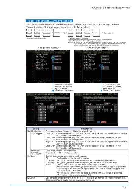
Trigger level settings/Alarm level settings<br />
Specifies detailed conditions for each channel when the start and stop side source settings are Level.<br />
The configuration of the level trigger is as shown in the figure below.<br />
CH n<br />
Mode<br />
Level<br />
CH n<br />
Mode<br />
Level<br />
Pulse n<br />
Mode<br />
Level<br />
Combination<br />
Trigger<br />
Pulse n<br />
Mode<br />
Level<br />
<br />
Alarm output n<br />
Logic n<br />
Mode<br />
Lower-Level-Upper<br />
Logic n<br />
* Pulse and Logic are switchable. * Pulse and Logic are switchable.<br />
* Specify an alarm output destination for each channel and Pulse/Logic.<br />
Each of the alarms is ORed at the output destination.<br />
Example: If you specify 1 as the output destination of 1CH and 2CH and 2 as that of 3CH and<br />
4CH, Alarm Output 1 occurs when one of 1CH and 2CH meets the conditions, and<br />
Alarm Output 2 occurs when one of 3Ch and 4CH meets the conditions.<br />
<br />
Mode<br />
Level<br />
<br />
Place the cursor here<br />
and press the ENTER<br />
key to open the<br />
following setting screen.<br />
Place the cursor here<br />
and press the ENTER<br />
key to open the<br />
following setting screen.<br />
Setting<br />
Description<br />
(1) Combination<br />
<br />
Sets a combination of trigger conditions set for each channel.<br />
Level OR : Starts (stops) capturing data when at least one of the specified trigger conditions is met.<br />
Each condition is Level operation.<br />
Level AND : Starts (stops) capturing data when all of the specified trigger conditions are met.<br />
Each condition is Level operation.<br />
Edge OR : Starts (stops) capturing data when at least one of the specified trigger conditions is met.<br />
Each condition is Edge operation.<br />
Edge AND : Starts (stops) capturing data when all of the specified trigger conditions are met.<br />
Each condition is Edge operation.<br />
Detection Level: Each condition is Level operation.<br />
method Edge: Each condition is Edge operation.<br />
<br />
(2) Mode Sets a trigger comparison mode for each channel.<br />
Off : Disables triggers for the setting channel.<br />
↑H (rising) : A trigger is generated when the input signal exceeds the specified level.<br />
↓L (falling) : A trigger is generated when the input signal falls below the specified level.<br />
Win In : Used to specify the upper and lower limits for each channel.<br />
When the input signal level is (or comes) between these limits, a trigger is generated.<br />
* This setting is not available for Logic CH.Win Out: Used to specify the upper and<br />
lower limits for each channel.<br />
When the input signal level is (or goes) out of these limits, a trigger is generated.<br />
* This setting is not available for Logic CH.<br />
(3) Level Sets a trigger comparison level. If the mode is ↑H (rising) or ↓L (falling), set one comparison level.<br />
If the mode is Win In or Win Out, set two comparison levels.<br />
3−31