Owner's Manual
Owner's Manual
Owner's Manual

Create successful ePaper yourself
Turn your PDF publications into a flip-book with our unique Google optimized e-Paper software.
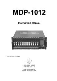
Names of Things and What They Do<br />
6. TIME Knob ...................................................................... (p. 23)<br />
Enables setting of the time for the video to fade when the OUTPUT FADE<br />
button is pressed. Time can be set from 0.0 to 4.0 seconds.<br />
* You can adjust the fadeout level by selecting "1. HD/RGB Output"<br />
(p. 48) in the menu and setting "12. Output Fade Mode" to<br />
"<strong>Manual</strong>."<br />
7. OUTPUT FADE Button ................................................... (p. 23)<br />
Press the OUTPUT FADE button to fade out the video output from the<br />
HD OUT connectors or RGB OUT connectors (p. 19).<br />
The status of FADE OUT can be determined by viewing the OUTPUT<br />
FADE button’s light.<br />
Button<br />
Flashing<br />
Lit<br />
Off<br />
Video Output Mode<br />
Fading out<br />
Black video output<br />
(Normal output)<br />
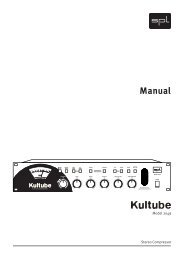
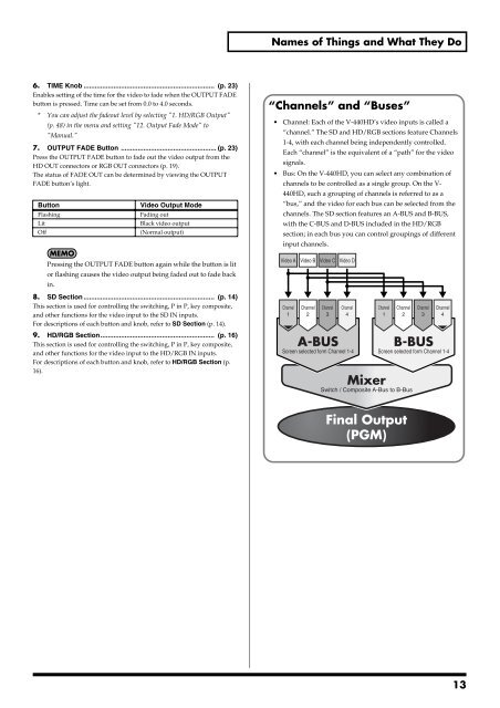
“Channels” and “Buses”<br />
• Channel: Each of the V-440HD’s video inputs is called a<br />
“channel.” The SD and HD/RGB sections feature Channels<br />
1-4, with each channel being independently controlled.<br />
Each “channel” is the equivalent of a “path” for the video<br />
signals.<br />
• Bus: On the V-440HD, you can select any combination of<br />
channels to be controlled as a single group. On the V-<br />
440HD, such a grouping of channels is referred to as a<br />
“bus,” and the video for each bus can be selected from the<br />
channels. The SD section features an A-BUS and B-BUS,<br />
with the C-BUS and D-BUS included in the HD/RGB<br />
section; in each bus you can control groupings of different<br />
input channels.<br />
Pressing the OUTPUT FADE button again while the button is lit<br />
Video A<br />
Video B<br />
Video C<br />
Video D<br />
or flashing causes the video output being faded out to fade back<br />
in.<br />
8. SD Section ...................................................................... (p. 14)<br />
This section is used for controlling the switching, P in P, key composite,<br />
and other functions for the video input to the SD IN inputs.<br />
For descriptions of each button and knob, refer to SD Section (p. 14).<br />
Channel<br />
1<br />
Channel<br />
2<br />
Channel<br />
3<br />
Channel<br />
4<br />
Channel<br />
1<br />
Channel<br />
2<br />
Channel<br />
3<br />
Channel<br />
4<br />
9. HD/RGB Section............................................................. (p. 16)<br />
This section is used for controlling the switching, P in P, key composite,<br />
and other functions for the video input to the HD/RGB IN inputs.<br />
For descriptions of each button and knob, refer to HD/RGB Section (p.<br />
16).<br />
A-BUS<br />
Screen selected form Channel 1-4<br />
B-BUS<br />
Screen selected form Channel 1-4<br />
Mixer<br />
Switch / Composite A-Bus to B-Bus<br />
Final Output<br />
(PGM)<br />
13