Basic Stamp 2 Robot Programming - ISL
Basic Stamp 2 Robot Programming - ISL
Basic Stamp 2 Robot Programming - ISL

Create successful ePaper yourself
Turn your PDF publications into a flip-book with our unique Google optimized e-Paper software.
<strong>Basic</strong> <strong>Stamp</strong> 2 <strong>Robot</strong> <strong>Programming</strong> 6-3<br />
+5-Volt<br />
Power<br />
Voltage<br />
Regulator<br />
Unregulated<br />
Power In<br />
8/16 I/O<br />
Pins<br />
Microchip<br />
PICMicro (R)<br />
or Scenix SX<br />
Microcontroller<br />
<strong>Programming</strong><br />
Interface<br />
SEEPROM<br />
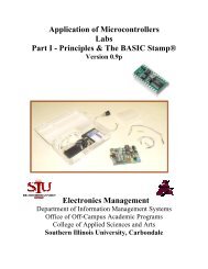
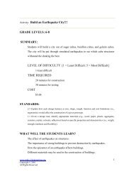
Figure 6-1<br />
Block diagram of Parallax “<strong>Basic</strong> <strong>Stamp</strong>.”<br />
Electronics Build Your Own <strong>Robot</strong> Kit is designed to work with, is programmed serially<br />
via a PC’s RS-232 interface.<br />
The program (or “application”) code is developed on a PC using a Windows-compatible<br />
editor/development system known as “stampw.” BASIC applications are created<br />
using this tool and then compiled into the series of instructions that are executed by the<br />
BASIC <strong>Stamp</strong>. I usually refer to these instructions as “tokens” as they represent BASIC<br />
functions and statements, but they are not the actual instructions executed by the microcontrollers<br />
built into the BASIC <strong>Stamp</strong>. In the following sections, I will demonstrate<br />
how applications are developed using “stampw” on a PC and how they are loaded into<br />
the BASIC <strong>Stamp</strong> 2 plugged into the TAB Electronics Build Your Own <strong>Robot</strong> Kit.<br />
The second feature that you should be aware of is that all BASIC <strong>Stamp</strong>s have a<br />
built-in voltage regulator to convert larger voltages into the correct voltages required<br />
by the microcontrollers built into the BASIC <strong>Stamp</strong>. These regulators are generally<br />
low-current with low parasitic power requirements that make them ideal for<br />
powering the BASIC <strong>Stamp</strong> plugged into the robot (in fact, the unregulated 9-volt<br />
power from the battery is used to drive the BASIC <strong>Stamp</strong> to avoid loading down the<br />
robot’s 78L05 voltage regulator). In addition to being able to drive the circuitry on<br />
the BASIC <strong>Stamp</strong>, these regulators generally have enough left over current for a few<br />
LEDs or simple logic chips.<br />
These regulators do not, however, have enough current to drive large loads. In<br />
recognition of this, and to protect the BASIC <strong>Stamp</strong>’s built-in voltage regulator, the TAB<br />
Electronics Build Your Own <strong>Robot</strong> Kit does not pass the BASIC <strong>Stamp</strong>’s regulated<br />
power to any other parts. As I will discuss below, for some applications, you will have to<br />
provide your own regulator circuit when you are adding circuitry to robot applications.<br />
As I stated above, the first BASIC <strong>Stamp</strong>s (“BS1s”) were programmed by a PC’s<br />
parallel port. This method for the most part works well, but it cannot insure that the<br />
connection will work with all PCs and parallel ports. The BASIC <strong>Stamp</strong> 2 (“BS2”) was<br />
designed to be programmed by a PC’s RS-232 serial port, which is a much more robust<br />
interface with very well-defined voltage levels and data rates.