Basic Stamp 2 Robot Programming - ISL
Basic Stamp 2 Robot Programming - ISL
Basic Stamp 2 Robot Programming - ISL
Create successful ePaper yourself
Turn your PDF publications into a flip-book with our unique Google optimized e-Paper software.
6-36 Chapter Six<br />
microcontroller and NMOS (a precursor to CMOS) circuits. These circuits could<br />
“sink” (pass to ground) a lot more current than they could “source” (pass from V cc<br />
or<br />
V dd<br />
). To follow this convention, I have wired the LEDs with their cathodes wired to<br />
the BS2 through the AppMod.<br />
The confusing aspect of wiring the LEDs in this way is that you must drive out a<br />
high voltage (a “1”) to turn off the LED and use a low voltage (a “0”) to turn it on. In<br />
the “Cylon Eye” application, I first put all the BS2’s I/O ports into “output mode” and<br />
then I write a “1” to each of the bits except for the least significant one. This will turn<br />
off all the LEDs except for the one connected to P0.<br />
I could have implemented the change in the active LED a number of different<br />
ways. I elected to shift the active bit up and down by multiplication and division. To<br />
move the LED from a lower bit to a higher bit, I multiplied the value in the 16 I/O pins<br />
by 2 and added 1 to the result to ensure that the least significant bit would be a “1.”<br />
Remember that the value in the I/O port is an odd number, and when you multiply an<br />
odd number by two, you get an even number.<br />
To go “down” the LEDs, I reversed the process by dividing the value in the I/O<br />
port by two and adding 32,768, which sets the high bit of the I/O port: 2 to the power<br />
15 equals 32,768.<br />
While I’ve taken into account that the port is sixteen bits in size, note that I kept<br />
the bits that I wrote to within the range of the ten LEDs that I wired to the AppMod<br />
board. I am pointing this out because while there are sixteen possible bits available<br />
to the AppMod board from the BS2, the most significant two bits (bits 14 and 15) are<br />
used for communications with the TAB Electronics Build Your Own <strong>Robot</strong> Kit.<br />
This means that if you want to “extend” the application with more LEDs you would<br />
be limited to 14 bits and not the full 16 available to the BS2.<br />
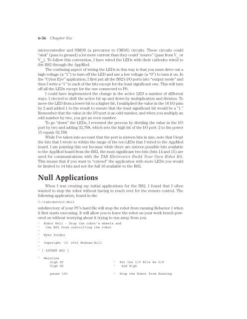
Null Applications<br />
When I was creating my initial applications for the BS2, I found that I often<br />
wanted to stop the robot without having to reach over for the remote control. The<br />
following application, found in the<br />
C:\tabrobotkit\Null<br />
subdirectory of your PC’s hard file will stop the robot from running Behavior 1 when<br />
it first starts executing. It will allow you to leave the robot on your work bench powered<br />
on without worrying about it trying to run away from you.<br />
‘ <strong>Robot</strong> Null - Stop the robot’s wheels and<br />
‘ the BS2 from controlling the robot<br />
‘<br />
‘ Myke Predko<br />
‘<br />
‘ Copyright (C) 2001 McGraw-Hill<br />
‘<br />
‘ { $STAMP BS2 }<br />
‘ Mainline<br />
high SC<br />
‘ Set the I/O Bits As O/P<br />
high SD ‘ and High<br />
pause 100<br />
‘ Stop the <strong>Robot</strong> from Running


