Basic Stamp 2 Robot Programming - ISL
Basic Stamp 2 Robot Programming - ISL
Basic Stamp 2 Robot Programming - ISL

You also want an ePaper? Increase the reach of your titles
YUMPU automatically turns print PDFs into web optimized ePapers that Google loves.
6-6 Chapter Six<br />
The “SOUT,” “SIN,” and “ATN” pins are used for programming the BS2 and can<br />
be used for an RS-232 interface. The “ATN” pin is connected to the programming<br />
PC’s “DTR” pin and is used to reset the BS2 for programming. If ATN is not active<br />
when the BS2 powers up, then the application already stored in the BS2 starts executing<br />
automatically. This feature is very useful since it allows you to program the robot<br />
and then try it out somewhere else.<br />
The remaining 16 pins of the BS2 are the I/O pins. These are bidirectional CMOS<br />
input and output pins, each with the ability of sinking and sourcing approximately 20<br />
mA. Total current sunk or sourced by the BS2 should not exceed 75 mA to ensure<br />
that the BS2’s voltage regulator is not overloaded.<br />
There are a number of different ways of accessing the BS2’s I/O pins. They can<br />
be accessed directly, as if they were variables, by using one of the predefined values<br />
listed below:<br />
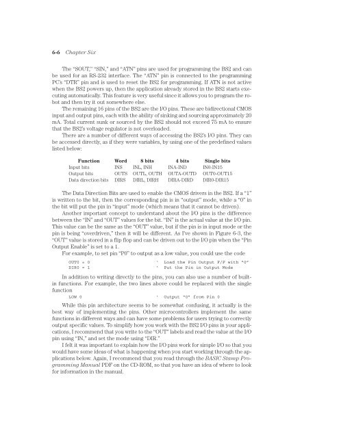
Function Word 8 bits 4 bits Single bits<br />
Input bits INS INL, INH INA-IND IN0-IN15<br />
Output bits OUTS OUTL, OUTH OUTA-OUTD OUT0-OUT15<br />
Data direction bits DIRS DIRL, DIRH DIRA-DIRD DIR0-DIR15<br />
The Data Direction Bits are used to enable the CMOS drivers in the BS2. If a “1”<br />
is written to the bit, then the corresponding pin is in “output” mode, while a “0” in<br />
the bit will put the pin in “input” mode (which means that it cannot be driven).<br />
Another important concept to understand about the I/O pins is the difference<br />
between the “IN” and “OUT” values for the bit. “IN” is the actual value at the I/O pin.<br />
This value can be the same as the “OUT” value, but if the pin is in input mode or the<br />
pin is being “overdriven,” then it will be different. As I’ve shown in Figure 6-3, the<br />
“OUT” value is stored in a flip flop and can be driven out to the I/O pin when the “Pin<br />
Output Enable” is set to a 1.<br />
For example, to set pin “P0” to output as a low value, you could use the code<br />
OUT0 = 0 ‘ Load the Pin Output F/F with “0”<br />
DIR0 = 1<br />
‘ Put the Pin in Output Mode<br />
In addition to writing directly to the pins, you can also use a number of builtin<br />
functions. For example, the two lines above could be replaced with the single<br />
function<br />
LOW 0 ‘ Output “0” from Pin 0<br />
While this pin architecture seems to be somewhat confusing, it actually is the<br />
best way of implementing the pins. Other microcontrollers implement the same<br />
functions in different ways and can have some problems for users trying to correctly<br />
output specific values. To simplify how you work with the BS2 I/O pins in your applications,<br />
I recommend that you write to the “OUT” labels and read the value at the I/O<br />
pin using “IN,” and set the mode using “DIR.”<br />
I felt it was important to explain how the I/O pins work for simple I/O so that you<br />
would have some ideas of what is happening when you start working through the applications<br />
below. Again, I recommend that you read through the BASIC <strong>Stamp</strong> <strong>Programming</strong><br />
Manual PDF on the CD-ROM, so that you have an idea of where to look<br />
for information in the manual.