Basic Stamp 2 Robot Programming - ISL
Basic Stamp 2 Robot Programming - ISL
Basic Stamp 2 Robot Programming - ISL

You also want an ePaper? Increase the reach of your titles
YUMPU automatically turns print PDFs into web optimized ePapers that Google loves.
<strong>Basic</strong> <strong>Stamp</strong> 2 <strong>Robot</strong> <strong>Programming</strong> 6-5<br />
As far as the TAB Electronics Build Your <strong>Robot</strong> Kit is concerned, the<br />
“SHIFTIN” and “SHIFTOUT” instructions allow very simple bits of code to be used<br />
for the BS2 to communicate with and control the robot. Other built-in functions allow<br />
the BS2 to communicate with other devices in a variety of different ways and use<br />
different standard protocols. Along with this, the BS2 PBASIC language allows for<br />
much more complex assignment and “if” statements, giving you more flexibility with<br />
your applications.<br />
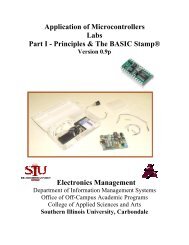
I think the best way to describe the BS2 is to look at its “pinout” (how the pins<br />
are arranged) as well as the function of each of the different pins. The BS2 plugs into<br />
a standard 0.600” (600 mil) Dual In-line Package (“DIP”) socket with the features<br />
and pins shown in Figure 6-2.<br />
When you are working with any kind of electronic chip, it is important to know<br />
where “Pin 1” is. This pin indicates how the chip is to be installed in the circuit. In<br />
some chips, Pin 1 is indicated with a dot beside it. In the BS2, the semicircular mark<br />
at the “top” of the chip indicates the end that Pin 1 is at. When the BS2 is installed<br />
in the robot, this semicircular mark should be used to line up with the similar mark<br />
that has been placed on the white marking (known as “silkscreen”) on the TAB Electronics<br />
Build Your Own <strong>Robot</strong> Kit printed circuit board.<br />
The other pins on the board are numbered by incrementing counterclockwise<br />
(looking from the top) from Pin 1. Using this convention, Pin 2 (“SIN”) is the pin beside<br />
Pin 1, Pin 3 (“ATN”) is beside Pin 2, and so on to Pin 24 (“VIN”), which is directly<br />
across from Pin 1. This numbering convention is used for all DIP chips (and<br />
many others of different technologies).<br />
Unregulated power is applied to the BS2 through the “VIN” and “VSS” (often referred<br />
to as “Ground” or “Gnd”) pins. The regulator built into the BS2 converts the<br />
voltage applied at VIN to 5 volts and applies it to the parts on the BS2 as well as external<br />
parts via the “VDD” (sometimes referred to as the “Vcc”) pin. The BS2 can<br />
have 5 volts applied directly through the VDD pin if regulated power is already<br />
available in the application. As I said earlier, the BS2 is powered by the unregulated<br />
power supplied by the 9-volt battery and the BS2 regulated voltage is not available<br />
anywhere else in the robot.<br />
Pin 1<br />
SOUT<br />
SIN<br />
ATN<br />
VSS<br />
P0<br />
P1<br />
P2<br />
P3<br />
P4<br />
P5<br />
P6<br />
P7<br />
Pin 1<br />
Indicator<br />
VIN<br />
VSS<br />
_RES or RES<br />
VDD<br />
P15<br />
P14<br />
P13<br />
P12<br />
P11<br />
P10<br />
P9<br />
P8<br />
Figure 6-2<br />
Parallax BASIC <strong>Stamp</strong> 2 pinout.