RED-D-ARC DC-600
RED-D-ARC DC-600
RED-D-ARC DC-600

Create successful ePaper yourself
Turn your PDF publications into a flip-book with our unique Google optimized e-Paper software.
A-5<br />
INSTALLATION<br />
A-5<br />
OUTPUT CONNECTIONS<br />
See Table A.1 for recommended <strong>DC</strong>-<strong>600</strong> cable sizes for combined lengths of electrode and work cables.<br />
TABLE A.1<br />
<strong>DC</strong>-<strong>600</strong> Cable Sizes for Combined Lengths of Copper Electrode and Work Cable<br />
at 100% Duty Cycle<br />
Cable Length<br />
Parallel Cables<br />
Cable Size<br />
Lengths up to 150 ft. (46m)<br />
2<br />
1/0 (53mm 2 )<br />
150 ft.(46m) to 200 ft (61m)<br />
2<br />
2/0 (85mm 2 )<br />
200 ft.(61m) to 250 ft.(76m)<br />
2<br />
3/0 (107mm 2 )<br />
ELECTRODE, WORK AND #21 LEAD<br />
CONNECTIONS<br />
A. Connect Electrode and Work Leads to<br />
Output Terminals.<br />
1. Set the ON/OFF toggle switch to OFF.<br />
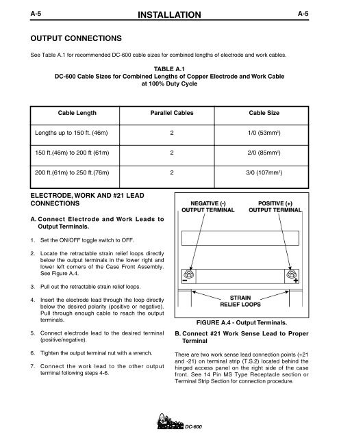
2. Locate the retractable strain relief loops directly<br />
below the output terminals in the lower right and<br />
lower left corners of the Case Front Assembly.<br />
See Figure A.4.<br />
3. Pull out the retractable strain relief loops.<br />
4. Insert the electrode lead through the loop directly<br />
below the desired polarity (positive or negative).<br />
Pull through enough cable to reach the output<br />
terminals.<br />
5. Connect electrode lead to the desired terminal<br />
(positive/negative).<br />
6. Tighten the output terminal nut with a wrench.<br />
7. Connect the work lead to the other output<br />
terminal following steps 4-6.<br />
FIGURE A.4 - Output Terminals.<br />
B. Connect #21 Work Sense Lead to Proper<br />
Terminal<br />
There are two work sense lead connection points (+21<br />
and -21) on terminal strip (T.S.2) located behind the<br />
hinged access panel on the right side of the case<br />
front. See 14 Pin MS Type Receptacle section or<br />
Terminal Strip Section for connection procedure.<br />
<strong>DC</strong>-<strong>600</strong>