RED-D-ARC DC-600
RED-D-ARC DC-600
RED-D-ARC DC-600

You also want an ePaper? Increase the reach of your titles
YUMPU automatically turns print PDFs into web optimized ePapers that Google loves.
F-5<br />
DIAGRAMS<br />
F-5<br />
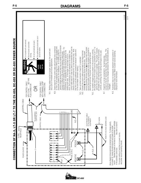
CONNECTION OF NA-3, LT-5 OR LT-7 TO THE CV-655, <strong>DC</strong>-655 OR <strong>DC</strong>-<strong>600</strong> POWER SOURCE<br />
14-PIN<br />
RECEPTACLE<br />
POWER SOURCE<br />
CONTROL CABLE<br />
FOR CONTROL CABLE<br />
WITH 14 PIN MS-TYPE<br />
PLUG CONNECTOR<br />
Do not operate with covers removed.<br />
Disconnect power source before<br />
servicing.<br />
21<br />
TO AUTOMATIC<br />
CONTROL BOX<br />
CONTROL CABLE<br />
OR<br />
FOR CONTROL CABLE<br />
WITH TERMINAL STRIP<br />
LEAD CONNECTORS<br />
Do not touch electrically live parts.<br />
Only qualified persons should install, use or<br />
service this machine.<br />
+21-<br />
N.F.<br />
21<br />
41 4 2 31 32 75 76 77<br />
N.B. & N.C.<br />
NEGATIVE POSITIVE<br />
N.D.<br />
physically suitable for the installation. An S16586-[LENGTH]<br />
77 remote voltage sensing work lead may be ordered for this purpose.<br />
76<br />
75<br />
32<br />
31<br />
2<br />
4<br />
GND<br />
21<br />
N.A. Welding cables must be of proper capacity for the current and<br />
duty cycle of immediate and future applications.<br />
or from 14-pin receptacle using #14 AWG or larger insulated wire<br />
N.B. Extend lead #21 from control cable with terminal strip connectors<br />
Connect it directly to the work piece keeping it electrically<br />
separate form the welding work lead circuit and connection. For<br />
convenience, this extended #21 lead should be taped to the<br />
welding work lead. (If the length of work lead circuit is<br />
short, and connections can be expected to be reliable, then<br />
control cable lead #21 does not need to be extended and can be<br />
directly connected to terminal #21 on the terminal strip. Note<br />
that this is not the preferred connection because it adds error<br />
to the wire feeder voltmeter reading.)<br />
N.C. Tape up bolted connection if lead #21 is extended.<br />
N.G.<br />
ELECTRODE CABLE<br />
TO AUTOMATIC<br />
EQUIPMENT<br />
N.D. Connect the control cable ground lead to the frame terminal<br />
marked near the power source terminal strip. The power<br />
source grounding terminal (marked and located near the power<br />
source input power connections) must be properly connected to<br />
electrical ground per the power source operating manual.<br />
N.A.<br />
TO WORK<br />
N.E. If a variable voltage board is present in the automatic controls,<br />
the jumper lead on the VV board must be connected to pin "L" to<br />
permit the inch down button to operate. This jumper, however,<br />
will disable the cold starting/autostop feature of the automatic<br />
controls, permitting only hot starting techniques to be used.<br />
REMOTE VOLTAGE SENSING LEAD<br />
Above diagram shows electrode connected positive. To change polarity,<br />
turn power off, reverse the electrode and work leads at the power<br />
source. Reverse the leads on the back of the ammeter and voltmeter<br />
in the automatic control box. Also refer to note N.F.<br />
N.F.<br />
If lead #21 is to be connected to the terminal strip,<br />
connect to the #21 terminal that matches work polarity. This<br />
connection must be changed whenever the electrode polarity is<br />
changed.<br />
N.G. Illustration does not necessarily represent actual position of<br />
appropriate output studs. Refer to power source operating<br />
manual for more information.<br />
For proper setting of switches on power source,<br />
see power source operating manual.<br />
10-30-98F<br />
S22978<br />
<strong>DC</strong>-<strong>600</strong>